Zeven Development
 This is an image title
 This is an image title
 This is an image title
 This is an image title
 This is an image title

IO Expander Plus
Checkout Our New Store!
www.ioexpanderplus.com
www.store.zevendevelopment.com
Order from our new store and get volume discounts!
*** We no longer sell International on Ebay. Please use our new store instead. ***
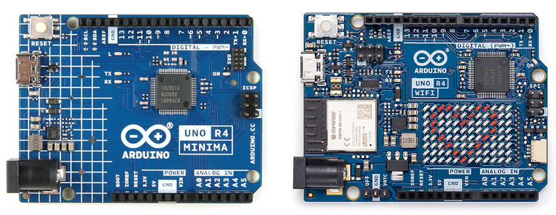
Fully Supporting the Arduino UNO R4; Even 9-bit!
See our Fix Your Arduino UNO R4 UART Issues Project
New Z-Wire to I2C/IO Now Shipping!
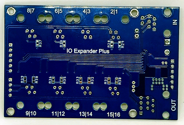
New IO Expander Plus v1.5 PCB Now Shipping!
With new pullup resistor pads added for available ports on the back side of the PCB. Populate the pads with 2.2K resistors to add additional Z-Wire or 1-Wire® buses.
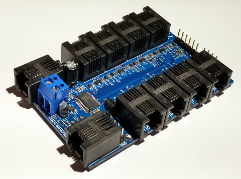
The New IO Expander Plus is Finally Here!
| IO Expander (v1.18) | IO Expander Plus (v2.0) |
|---|---|
| Microchip PIC16 | Microchip PIC18 |
| 32MHz | 64MHz. Twice the speed. |
| 125ns Minimum Instruction Cycle | 62.5ns Minimum Instruction Cycle. |
| 49 Instructions | 81 Instructions. Smaller code compile size. |
| 16-Level Deep Hardware Stack | 31-Level Deep Hardware Stack. Additional function call nesting. |
| 10-bit ADC | 12-bit ADC. Increased Resolution. |
| Single Shared Interrupt | Vectored Interrupt Controller. Faster Interrupt Processing |
| Bootloader Shared with Program | Hardware Protected Bootloader. Additional Code Security. |
| 56KB Flash Program Memory | 128KB Flash Program Memory. Double the Program Code Size for Additional Sensor Support. |
| 4KB Data SRAM | 8KB Data SRAM. Double the Memory. |
| 256B of EEPROM | 1KB of EEPROM. Four Times the NVM Storage. |
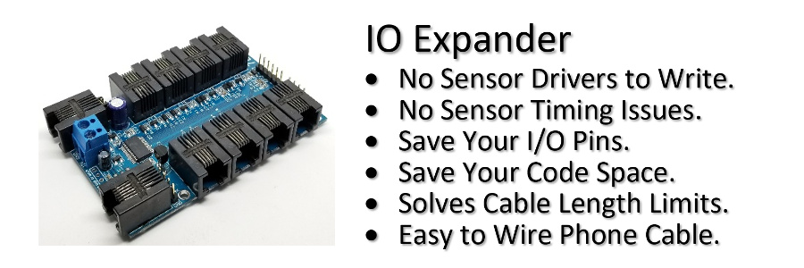
IO Expander, the Distributed Sensor Controller
Tired of writing drivers for sensors?
Are you spending hours debugging driver code?
Run out of I/O pins and code space because your sensor drivers took it all?
Sensors can't reach their destination due to bus length limitations?
Then the IO Expander is for you! This unique interface board removes the complexity of connecting sensors to your project and allows you to focus your time on using sensors to solve your problem. Highly expandable this small board allows you to connect almost any combination and number of sensors.
New Firmware v2.4 available!
Arduino (Now Supporting Arduino UNO R4!)
IO Expander v1.4 Library Download! (New Advanced Serial/Telnet Debug Control!)
IO Expander 9-bit v1.4 Library Download!
(New Advanced Serial Debug Control!)
Raspberry Pi
IO Expander v1.1 Python Module Download!
(New Advanced Serial/Telnet Debug Control!)
IO Expander 9-bit v1.1 Python Module Download!
(New Advanced Serial/Telnet Debug Control!)
Feature List
- 16 Digital IO/ADC Sensor lines.
- 4 additional relay control lines. Use the Relay Expander to control up to 256 relays.
- Overvoltage and up to 30kV ESD protection on all 16 IO lines.
- Uses common RJ11 straight through phone cable to connect sensors.
- 115.2k N81 simple serial control protocol.
- Support for 9-bit multi-drop to connect up to 255 IO Expander boards together.
- Use the IO Extender to connect IO Expander boards together up to 4000 ft.
- Uses +2.7VDC to +18VDC 1A input to regulate +5V, or +5V external input to power board and sensors.
- Reverse polarity input protection.
- Thermal shutdown and then back on at 150°C.
- Firmware upgradeable over the internet.
- Supports our own Z-Wire or Maxim's 1-Wire® bus (Standard & Overdrive Speed with software-controlled active pull-up).
- Support for unlimited I2C devices using Z-Wire to I2C or 1-Wire® to I2C.
- Onboard temperature sensor.
- Easy interface to PC, MAC, Arduino, Raspberry Pi or any MCU with a serial port.
- Idle mode 9mA with 5V direct input, 8mA with 12V regulated input.
- 87.3mm x 58.4mm
Note: The IO Expander can support 16 1-Wire® buses, but will need a 2.2K external pullup on each line.
Sensors Supported
- Maxim 1-Wire® DS18B20,DS18S20,DS1822 Temperature.
- Maxim 1-Wire® Control.
- Maxim 1-Wire® DS28E17 to I2C.
- OneWire AM2302,DHT11,DHT22 Temperature/Humidity.
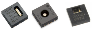
- Sensirion SHT1x Temperature/Humidity.
- 4 Relays or Relay Expander for 256 Relays.
- Flow (Hall Effect).
- GPIO Control.
- Float Switch (Magnetic and Optical).
- Button Input.
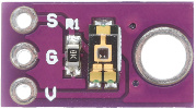
- Proximity Sensor. (New v1.14)
- Capacitive Soil Sensor.
- Ultrasonic HCSR04.
- ADC TEMT6000 Light.
- Sensirion I2C HTU2x,SHT2x,SHT3x Temperature/Humidity.
- I2C Control.
- Atlas Scientific EZO™ Circuit Flow/Temperature/pH/ORP/Dissolved Oxygen/Conductivity. (New v1.15)
- Silicon Labs I2C Si7021 Temperature/Humidity.
- Bosch I2C BMP180 Temperature/Pressure. (Depreciated v1.17)
- Bosch I2C BMP280 Temperature/Pressure. (New v1.17)
- Bosch I2C BME280 Temperature/Humidity/Pressure. (New v1.17)
- TAOS I2C TSL2561 Light. (Depreciated v1.17)
- Ti I2C LM75 Temperature.
- Maxim I2C DS3231 RTC/Temperature.
- Atmel I2C AT24C32 32Kbps Serial EEPROM.
- SSD1306 0.96", SSD1309 2.42" (New v1.14) I2C 128x64 Dot Matrix OLED/PLED Display.
- Microchip I2C MCP9600,MCP9601 Thermocouple Temperature.
- HX711 Load Cell Weight Sensor. (New v1.13)
- SH1106 1.3" I2C 128x64 Dot Matrix OLED/PLED Display. (New v1.13)
- TAOS I2C TSL2591 Light. (New v1.14)
- TAOS I2C TCS34725 RGB Light. (New v1.14)
- Sensirion I2C SCD30 CO2 Temperature/Humidity. (New v1.14)
- Sensirion I2C SCD40,SCD41 CO2 Temperature/Humidity. (New v1.17)
- 433MHz RF Transmitter. (New v1.16)
- PCF8574 8-bit I2C Expander. (New v1.17)
- ADS1015 12-bit 4-Channel ADC I2C Expander. (New v1.17)
- Analog Keypad. (New v2.1 Plus)
- TM1637 6 Digit LED Display. (New v2.1 Plus)
- ZGPIO 3-Channel ADC/IO. (New v2.1 Plus Z-Wire)
- HT16K33 16*8 LED Controller Driver. (New v2.1 Plus Z-Wire)
- MAX7219 8-Digit LED Display Driver. (New v2.2 Plus Z-Wire v1.3)
- INA260 Ti I2C Precision Digital Current and Power Monitor. (New v2.4)
- System Commands.
- Multiple IO Expanders.
- New sensors added with firmware updates.
The IO Expander will work with any MCU that has a serial port such as an Arduino Uno, Raspberry Pi, BeagleBone, PC, MAC, and many many other MCUs.
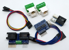
Starting out? Make sure you get your IO Expander Z-Wire Bundle with the IO Expander
So what does it take to connect and use the IO Expander?
A single serial port at 115200 baud, no parity, 8 data bits, 1 stop bit.
Let's connect a DHT22 Humidity/Temperature sensor to pin 6 and read
it.
Using very simple single character commands;
[s]ensor
on pin [6] of [t]ype [5][;] [s]ensor [r]ead.
>s6t5;sr
DHT22

			22.3
38.5
>
It's that simple to use!
Connect the IO Expander to an Arduino.
Let's connect an Arduino Nano to the header pins PL6 and read a DHT22 Humidity/Temperature sensor on pin 6.
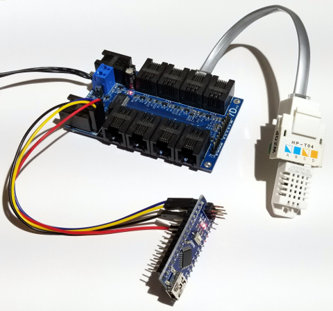
Arduino DHT22 Wiring Diagram
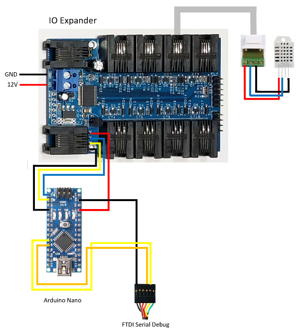
First we have to tell the IO Expander what pin we are using and the [t]ype of [s]ensor connected.
Then we tell the [s]ensor to [r]ead.
That was easy, and better yet it did not require us to use any sensor drivers! All the sensor drivers are already built into the IO Expander.
For additional information on the Arduino Nano and Family use this good Introduction to Arduino Nano.
Since the same serial port that is used for the IO Expander is also used by USB connector for programming, it is recommended to use the ICSP port on the Arduino Nano for programming using an AVR Programmer. For debugging use a software serial port on other pins on the Arduino Nano with a FTDI TTL-232R USB to Serial cable connected to your computer.
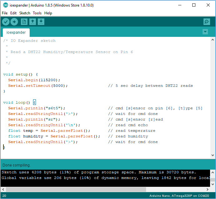
Use the optimized IOExpander library to further reduce the code size down to 2646 bytes (8%) of program storage space, and global variables use 198 byes (9%) of dynamic memory. Need help installing additional arduino libraries?
Download IOExpander.zip v1.4 library.
/* IO Expander sketch optimized

 *

 * Read a DHT22 Humidity/Temperature Sensor on Pin 6

 *

 */


#include <SoftwareSerial.h>

#include "IOExpander.h"


//#define SERIAL_DEBUG


#ifdef SERIAL_DEBUG

SoftwareSerial swSerial(8,7);

#endif


void setup() {

  Serial.begin(115200);

#ifdef SERIAL_DEBUG

  swSerial.begin(115200);

  swSerialEcho = &swSerial;

#endif

}


void loop() {

  float temp, humidity;


#ifdef SERIAL_DEBUG

  if (SerialDebugControl()) return;

#endif


  if (SerialCmdDone("s6t5")) {            // cmd [s]ensor on pin [6], [t]ype [5]

    SerialCmd("sr");                      // cmd [s]ensor [r]ead

    if (SerialReadFloat(&temp) &&         // read temperature

        SerialReadFloat(&humidity)) {     // read humidity

      SerialReadUntilDone();              // wait for cmd done

#ifdef SERIAL_DEBUG

      swSerial.println(temp, 1);

      swSerial.println(humidity, 1);

    }

    else swSerial.println(F("Error reading DHT22"));

  }

  else swSerial.println(F("IO Expander not found"));

#else

    }

  }

#endif

}
Connect the IO Expander to a Raspberry Pi.
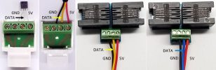
To connect the IO Expander to a Raspberry Pi we will need to use Level Converters since the Pi is not 5V tolerrent. To do this, use the Sparkfun Logic Level Converter Bi-Directional
Raspberry Pi DHT22 Wiring Diagram
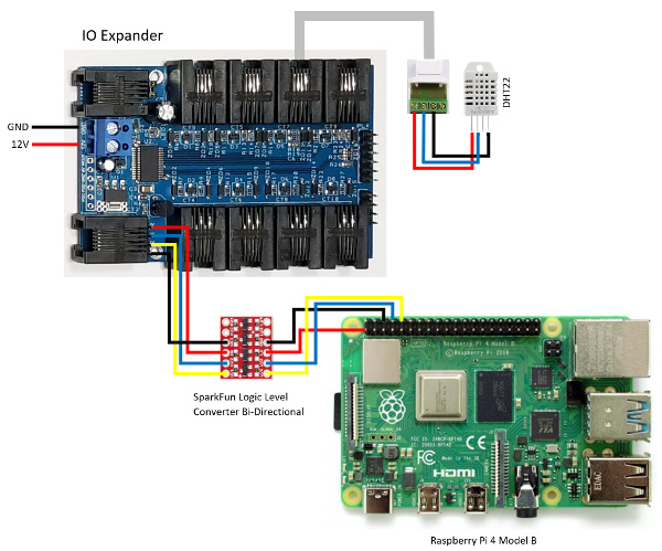
Note: Make sure that you have Enabled the Serial Port and Disabled the Serial Console in the Raspberry Pi Configuration/Interfaces
Using Python do a [s]ensor [r]ead.
Use the optimized IOExpander python module to make your programming easier!
Download ioexpander.py v1.1 module.
#!/usr/bin/env python

import ioexpander


ioexpander.ser.flushInput()


while 1:

    if ioexpander.TelnetControl(b''):

        continue


    ioexpander.SerialCmdDone(b's6t5')

    ioexpander.SerialCmd(b'sr')

    temp = ioexpander.SerialReadFloat()

    humidity = ioexpander.SerialReadFloat()

    ioexpander.SerialReadUntilDone()

    print(temp, ",", humidity)
If you are having trouble connecting to the IO Expander on your Pi, first check the communications using Minicom
New Advanced Serial/Telnet Debug Control
Advanced Debugging using an additional Serial Port and/or Remote Telnet connection is now possible.
Press the Escape Key to Enter/Exit IO Expander Mode; pause your program and access your IO Expander directly. After 60 seconds of inactivity it will automatically exit the IO Expander Mode so your program will continue running.
...
Entering IO Expander Mode
>t2f

			28ffe835c3160376
28ff6431c3160392
28ffb3b8a11605e0
>#s
3cd1301b26b014f9
>
Exiting IO Expander Mode
...
Connect to your IO Expander from anywhere using a Telnet connection. Press the 'c' key to close the Telnet connection, or 'r' to reset your NodeMCU board. Arduino default port is 23, Raspberry Pi is 1234.
			pi@raspberrypi:~ $ telnet 192.168.1.178 1234

			Trying 192.168.1.178...

			Connected to 192.168.1.178.

			Escape character is '^]'.

			>e1o

			ok

			>e1f

			ok

			>e2o

			ok

			>

			bye bye

			Connection closed by foreign host.

			pi@raspberrypi:~ $
Note: Telnet must be set to Character Mode and Local Echo.
On your Raspberry Pi use a Telnet connection in 9-bit mode, and finally be able to clearly see your commands prefixed by the board number. In IO Expander Mode you can now also send commands to different boards using 8-bit ASCII by also prefixing the command with the destination board number.
			...

			>1:e1o

			ok

			>1:e1f

			ok

			>1:e2o

			ok

			>

			Entering IO Expander Mode

			>1:#s

			2819000008860073

			>2:#s

			28a41aa10300009d

			>

			Exiting IO Expander Mode

			1:e2f

			>1:e3o

			ok

			...
IO Expander Diagram
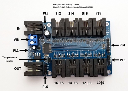
IN - RJ12 6P6C Input 5V,5V,Tx,Gnd,Rx,Gnd. Use the
5V input to power the board.
OUT - RJ12 6P6C Output
5V,5V,Tx,Gnd,Rx,Gnd. Connect to another IO Expander IN. The two outer
pins 1 and 6 are optional but recommended especially for longer runs
if using remote power.
| Pin | Function |
|---|---|
| 1 | 5V |
| 2 | 5V |
| 3 | Tx |
| 4 | Gnd |
| 5 | Rx |
| 6 | Gnd |
PL3 - Jumper to disable/enable 5V from IN. If you
power the 5V from the Relay or PL6 and have 5V on IN make sure this
jumper is removed.
VIN - +2.7VDC to +18VDC input
(Recommended 7VDC 1A). If there is 5V already on IN, it will automatically
switch to this input.
PL1 - ICSP programming port
for PICKIT3. Only used for production and board recovery. Firmware will
be updated via the internet.
PL6 - Quick connect
header for Arduino or development. Header 5V,Tx,Rx,Gnd.
8
Ports - RJ11 6P4C 5V,D1,Gnd,D2 sensor ports. There are two
data wires for each RJ11 because some sensors like the DHT22 require
2 pins to communicate. Other sensors such as the 1-Wire®
DS18B20 will only use 1 pin, which allows you to use a
Splitter and create two separate sensor
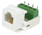
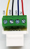
runs. To make wiring really easy use an RJ11 keystone screw terminal.
| Pin | Function | Logical Pins |
|---|---|---|
| 1 | NC | |
| 2 | 5V | |
| 3 | D1 | First 2,4,6,8,10,12,14,16 |
| 4 | Gnd | |
| 5 | D2 | Second 1,3,5,7,9,11,13,15 |
| 6 | NC |
PL4 (Relay) - Relay control port. The relay pins
5V,R1-R4,Gnd in addition to the port pins. Only connect the 5V pin if
you want to power the IO Expander from the Relay port. Also don't forget
to disable PL3 if you have 5V also connected to IN.
PL5 (HCSR04
Ultrasonic) - Quick connect header 5V,Trig,Echo,Gnd for the
HCSR04 Ultrasonic sensor. PL5 shares the pins with port pins 9
and 10. Additional HCSR04 Ultrasonic sensors can also be connected
to the other ports as well.
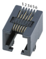
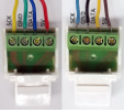
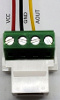
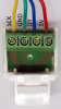
Simple to use 4P4C RJ11 Straight Through Phone Cable
The IO Expander and it's products mainly use 4 Position, 4 Conductor straight through phone cable. The exception is the IN and OUT on the IO Expander which uses a 6 Position, 6 Conductor straight through phone cable.
A straight through cable can be verified, if you hold both ends together on the same side, the wire color order will match.

IO Expander Control
A simple command structure is used to control the IO Expander
cmd[cmddata][subcmd[subdata]]
cmd - A single letter command. Not case sensitive.
| cmd | Function |
|---|---|
| d | Delay[ms] |
| e | Expander Relay |
| g | GPIO (Digital/Analog) |
| i | I2C 1-Wire® |
| o | 1-Wire® |
| r | Relay |
| s | Sensor |
| t | Temperature 1-Wire® |
| z | Z-Wire |
| # | System Commands |
| ? | Help |
cmddata - Decimal port pins (1-16), relay #, delay
ms. The system remembers the cmddata used in the previous command so
it's not necessary to keep repeating it.
subcmd
- Subcommand also a single letter. Not case sensitive.
subdata - Hexadecimal/Decimal/String data that may
be needed by the subcommand.
Note: Commands can be stacked by the ';' separator. Responses will also be stacked.
All commands are terminated by the Carriage Return CR (13) character unless in String Mode.
The IO Expander is ready to accept commands when the '>' character is displayed. You can only enter 128 (256 New v1.14) characters including the carriage return per line. There will always be a response, either 'ok', result, or error. Extended errors are prefixed with the charater 'E' and number and used for extended debugging purposes.
To allow for maximum flexibility to enter subdata the following commands are supported, that allow you so switch between hexadecimal, decimal, and string modes:
| subdata commands | Function |
|---|---|
| CR | Carriage Return (13) or EOL (End Of Line) |
| " | String Mode. To send the quote (34), backspace (8),
or CR (13) character, exit String Mode with another closing quote character and then use Hexadecimal or Decimal Mode. A comma after the closing quote is not necessary unless you need to switch to Decimal Mode. |
| ,:/[space] | Decimal Mode |
| ; | Command Separator |
| x | Hexadecimal Mode |
IO Expander Checksum
To validate communications an optional checksum can be added to the end of the command line. Add the pipe '|' character followed by the ascii hexadecimal CRC-8 x8 + x5 + x4 + 1 checksum. If the event of a communication corruption a 'crc' response will be sent instead.
To quickly find the checksum value use the '?' character
>s6t5;sr|?
c8
>
When you send a checksum byte the response will also be appended with a checksum byte delimited by the '|' character, that includes all the characters sent upto the pipe character including the '\r\n' after every line.
>s6t5;sr|c8
DHT22

			22.3
38.5
|76
>
IO Expander Sensors
A lot of different sensor types are directly supported by the IO Expander, connected either by Digital, ADC, 1-Wire® or I2C.
| # | Sensor Type |
|---|---|
| 1 | SHT1x Temperature/Humidity |
| 2 | HTU2x,SHT2x Temperature/Humidity |
| 3 | SHT3x Temperature/Humidity |
| 4 | DHT11 Temperature/Humdity |
| 5 | DHT22 Temperature/Humdity |
| 6 | HCSR04 Ultrasonic |
| 7 | TEMT6000 Light |
| 8 | Si702x Temperature/Humidity |
| 9 | TSL2561 Light |
| a | TL2561CS Light |
| b | BMP180 Temperature/Pressure |
| c | LM75 Temperature |
| d | Hall Effect |
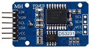
| e | DS3231 RTC |
| f | AT24C32 EEPROM |
| 10 | SSD1306 OLED Display |
| 11 | MCP9600 Thermocouple Temperature |
| 12 | HX711 Load Cell Weight |
| 13 | SH1106 OLED Display |
| 14 | TSL2591 Light |
| 15 | TCS34725 RGB Light |
| 16 | SCD30 CO2 Temperature/Humidity |
| 17 | 433MHz RF Transmitter |
| 18 | BMP280 Temperature/Pressure |
| 19 | BME280 Temperature/Humidity/Pressure |
| 1a | PCF8574 8-bit Expander |
| 1b | ADS1015 12-bit 4-Channel ADC Expander |
| 1c | SCD40,SCD41 CO2 Temperature/Humidity |
| 1d | Analog Keypad |
| 1e | TM1637 6 Digit LED Display |
| 20 | HT16K33 16*8 LED Controller Driver |
Use '?t' to display this sensor type list.
Maxim 1-Wire® DS18B20,DS18S20,DS1822 Temperature
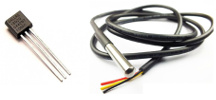
Use the 't' cmd to control these 1-Wire® temperature sensors. Pins 3 and 4 of the IO Expander already come equiped with a 2.2k pull-up resistor needed to operate 1-Wire® devices. You can add additional 1-Wire® busses to the other ports using the Splitter. 1-Wire® temperature sensors only support standard speed, but you can mix standard and overdrive speed devices on the same 1-Wire® bus. The IO Expander will automatically switch speeds depending on the detected device.
| subcmd | Function | Mode |
|---|---|---|
| a | Find Alarm flag set | |
| c[resolution[,high[,low]]] | Config[9,10,11,12[,temp high[,temp low]]] | Dec |
| f | Find only 1-Wire® temperature sensors | |
| r[ID] | Read[64-bit ID] | Hex |
| s[ID] | Select[64-bit ID] | Hex |
| t[ID] | Convert Temperature[64-bit ID] | Hex |
For this example we have connected four DS18B20s to pin 4 using 1-Wire® junctions.
First we need to [f]ind all the 1-Wire® [t]emperature sensors on pin [4]. This command will return all the unique 64-bit addresses of the temperature sensors.
>t4f
28fff4d6c4160413

			28ffb2422216031c
28ff6573d01605cb
28ffb3b8a11605e0
>
Next we need to [s]elect the 1-Wire® [t]emperature sensor we want to control. We don't need to specify pin 4 anymore. Also to select the sensor on the 1-Wire® bus we only need to specify the last unique bytes of the 64-bit address 28fff4d6c41604[13].
>ts13
28fff4d6c4160413
>
Now we need to start a [t]emperature conversion on the 1-Wire® [t]emperature sensor.
>tt
ok
>
Finally we tell the [t]emperature sensor to [r]ead the results.
>tr
23.25
>
Or we can stack all the commands into a single request. The IO Expander will automatically wait until the temperature measurement is ready to read.
>ts13;tt;tr
28fff4d6c4160413

			ok
23.3125
>
If we want to read all the temperature sensors we select no rom before a temperature conversion, which sends the command to all the sensors on the 1-Wire® bus. Finally we read each sensor by specifing the last unique 64-bit bytes. This will also select the sensor for you.
>ts0;tt;tr13;tr1c;trcb;tre0

			no rom
ok
22.75
22.5625
24.875
22.6875
>
To configure the [t]emperature sensor we need to first [s]elect it. Then display the [c]onfig by not specifing any subdata.
>ts13;tc
28fff4d6c4160413

			12
125
-55
>
The config returned the resolution, temperature high, and temperature low.
To configure just the [t]emperature sensor [c]onfig resolution to [9]-bit, and the temperature high below the current temperature comma delimited in decimal. Since these values are stored in nonvolatile storage they will retain their settings even if they are powered down, you only need to configure them one time.
>tc9,20
9
20

			-55
>
Now let's do a [t]emperature conversion on all the sensors, and find which ones are flaged as [a]larmed.
>ts0;tt;ta
no rom

			ok
28fff4d6c4160413
>
Maxim 1-Wire® Control
You can also communicate with any 1-Wire® device directly using the 'o' cmd.
| subcmd | Function | Mode |
|---|---|---|
| d[ms] | Wait Done def=1000ms | Dec |
| f | Find all 1-Wire® devices | |
| o[n] | Speed[0-Standard,1-Overdrive] | |
| r[n] | Read[# of bytes] | Hex |
| s[ID] | Select[64-bit ID] | Hex |
| t | Reset | |
| w[bytes] | Write data | Hex |
Let's read the 1-Wire® temperature sensor 28fff4d6c4160413 by using direct 1-Wire® commands
>ot
ok
>ow55

			ok
>ow28fff4d6c4160413
ok
>ow44
ok
>ot
ok
>ow55

			ok
>ow28fff4d6c4160413
ok
>owbe
ok
>or9
800114c91fff1f10e0
>
Or a more compact method.
>os13;ow44;od;os13;owbe;or9

			28fff4d6c4160413
ok
ok
28fff4d6c4160413
ok
c00114c91fff1f10a9
>
Note: When using standard and overdrive devices on the same 1-Wire® bus use the 'o' subcommand to switch to standard speed to find all the devices.
Maxim 1-Wire® DS28E17 to I2C.
OneWire AM2302,DHT11,DHT22 Temperature/Humidity.
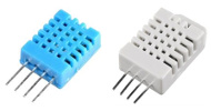
Another type of OneWire sensor is the AM2302,DHT11,DHT22. To communicate with most sensors of the IO Expander we will need to use the 's' cmd. This sensor is type 4 and 5. Pins 6 and 8 of the IO Expander already come equiped with a 5.1k pull-up resistor and 1000pF filter capacitor to Gnd needed to operate this type of OneWire device. You can add additional OneWire sensors to the other ports using the Splitter.
| subcmd | Function |
|---|---|
| r | Read |
| t4/t5 | Type DHT11/DHT22 |
Lets [r]ead a DHT22 [s]ensor on pin 6.
>s6t5;sr
DHT22

			23.2
34.1
>
The read returned the temperature in °C and humidity in %.
Sensirion SHT1x Temperature/Humidity.
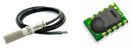
This sensor requires two wires SCK and DATA to communicate, and will only allow you to select an even pin for SCK, pairing with the odd pin for DATA. This sensor is type 1. It requires a 10k pull-up on the DATA pin.
| subcmd | Function |
|---|---|
| r | Read |
| t1 | Type SHT1x |
Lets [r]ead a SHT10 [s]ensor on pin 7 (DATA) and 8 (SCK).
>s8t1;sr
SHT1x

			23.64
49.8419
>
The read returned the temperature in °C and humidity in %.
4 Relays or Relay Expander for 256 Relays.
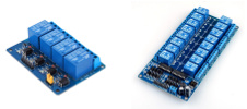
The IO Expander can control a single x4 relay board or using the Relay Expander control up to 16, x16 relay boards. You can use the IO Expander to power the x4 relay board, or you can power the IO Expander from the x16 relay board, otherwise do not connect the 5V pin. If you want to control a x4 relay board make sure that the number of Relay Expander boards is also set to zero; 'eb0'.
| subcmd | Function | Mode |
|---|---|---|
| f | Off | |
| g | Get bits (New v1.14) | Hex |
| o | On | |
| s(bits) | Set bits | Hex |
Let's turn [r]elay [1] [o]n.
>r1o
ok
>
Now turn [r]elay [1] of[f].
>r1f
ok
>
If we want to set all the relays on/off with a single command, then use the hexadecimal bit equivalent, with the lsb being relay 1. Since the relays are active low, 0 is on and 1 is off.
Let's [s]et relay 1 and 3 on. Binary 1010 is [a] in hexadecimal.
>rsa
ok
>
Note: To drive all 4 relays at the same time make
sure that you have powered it with 7V on VIN or 5V on IN.
If you
use 12V on VIN, the maximum current that can be delivered is I = 2 /
(12-5) = 285mA.
However if using 7V on VIN, the maximum current is
I = 2 / (7-5) = 1A.
Flow (Hall Effect).
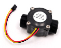
Since there are many different sizes of flow sensors and they use the same type of Hall Effect sensor, the IO Expander will return the number of revolutions in a given time duration, which will allow you to calculate the flow rate. This is effectively a negative edge counter.
| subcmd | Function | Mode |
|---|---|---|
| r[ms] | Read[wait in ms] (New v1.14) | Dec |
| td | Type HALL |
Let's [r]ead the flow in 1000 ms on pin [2].
>s2td;sr1000
HALL

			ok
7
>
We used a FS300A G3/4" 1-60L/min, so at 5.5 pulses for every liter of liquid passing through it; 7/5.5 = 1.27 L/min. By specifing a wait time the negative edge interrupt counter is first set to zero and then counts for the wait time specified. This is the flow rate for that second in time.
(New v1.14)
But if you would like to measure
the amount of flow for a much longer time duration then at the start
specifiy a wait time of zero to clear the negative edge interrupt counter.
Then after the time duration do not specify any wait time and it will
return the current negative edge interrupt count. Using this count we
can calculate the amount of flow during the time duration. This would
be similar in operation to your water meter counter. The negative edge
counter is not cleared but continues counting until you specify a wait
time of zero again.
Let's clear the negative edge interrupt counter to zero
>s2td;sr0
HALL

			0
>
After one hour we [r]ead the sensor again.
>s2td;sr
HALL

			134
>
So after counting for one hour 134/5.5 = 24.36 liters of liquid has passed through the flow sensor. To remove the negative edge counter on the pin use the gpio 'gi' cmd to set it back to an input only pin.
Note: If you are not using an external 10k pullup don't forget to add a weak pullup 'gw1' to your pin.
GPIO Control
The next sensors take advantage of the GPIO control.
| subcmd | Function | Mode |
|---|---|---|
| a[count] | Analog Read[1-255 Count Average] (New v1.14) | Dec |
| d[input,time] | Debounce[input(0-Low,1-High),time in ms | Dec |
| e | Edge Count Read (New v1.14) | |
| i | Input Read | |
| n | Negative Edge | |
| o(0,1)[,[...]] | Output Level (0-Low,1-High)[,duration in ms[...]] (New v1.14) | Dec |
| p | Positive Edge | |
| t[pin] | Time in µs [pin delta] (New v1.14) | Dec |
| w(0,1) | Weak Pull-Up (0-Disable,1-Enable) |
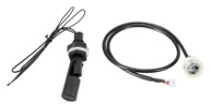
Float Switch (Magnetic and Optical).
Float switches use the 'g' cmd for GPIO control.
Since we normally connect the float sensor to gnd we will need to use a weak pull-up on the pin.
Let's setup a float sensor with a [w]eak pull-up on pin [12] and read the [i]nput on an open float sensor.
>g12w1;gi
ok
1
>
Now let's close the float switch and read the [i]nput again.
>gi
0
>
We can also setup the GPIO to be negative edge triggered, which will allow us to monitor if the switch ever closed since the last reading.
Let's setup a detect on a [n]egative edge and do an [e]dge read.
>gn;ge
ok
0
>
Now let's close the switch and then open it again before we do another [e]dge read.
>ge
1
>
The GPIO edge read return 1 even though the float is open because a negative edge occured since the last read. Performing an edge read will clear the value for the next edge read. To remove edge triggered on a pin use the 'i' subcmd to set it back to an input only pin.
The optical level sensor works the same way as the float switch but use the Optical Connector for a quicker worry free installation.
Button Input
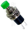
If you need to add debounce logic to a button input use the 'd' subcmd specifing the logic level to detect and how long it must be held before it detects a trigger. For reading a debounce trigger just call the 'd' subcmd with no subdata.
Let's setup a button input with a [w]eak pull-up on pin [12] and a debounce to detect a low for 75ms and read it. Debounce setup is only required one time. You can just call 'gd' for subsequent reads.
>g12w1;gd0,75;gd

			ok
ok
0
>
We can remove the debounce by specifying a detect time of zero.
>g12d0,0
ok
>
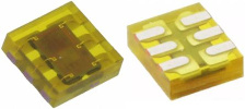
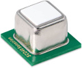
Proximity Sensor (New v1.14)
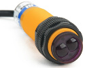
Need to detect movement then use a proximity sensor. Use the gpio 'n' subcmd to setup a negative edge, then use the gpio 't' subcmd to find the first time is was triggered.
Let's set a [n]egative edge on pin [7] of a proximity sensor that uses an internal pull-up resistor. If the sensor is not activated it will return zero, otherwise if activated it will return the [t]ime in the number of milliseconds and microseconds since the IO Expander was last reset.
>g7n;gt
ok
0

>gt
11119
77
>
The time returned is the number of milliseconds (ms) and microseconds (µs) since the IO Expander was last reset. To clear the time to do another trigger, do an [e]dge read.
>ge
1
>gt

			0
>
To detect speed you can also setup multiple proximity sensors and find the delta time between activations.
Let's setup two proximity sensors on pins 7 and 8. Then activate them both in sequence and determine the time it took between them. If the distance is known, you will be able to calculate the speed.
>g7n;g8n
ok
ok

>g7t8
146579
>
The time returned is the delta time between the proximity sensors being triggered on pin 7 and 8 in microseconds (µs). If you need to check when a timing event has occured read the pin 8 time until it is not zero before reading the delta time otherwise you may read a negative delta time if you read between the event where pin 7 has a time but pin 8 has not yet triggered.
Note: If you are using a proximity sensor or a mechanical trigger that does not have a pull-up, you will need to add an external one or use the 'w1' subcmd to add a weak pull-up to the input pin otherwise it will be floating and may not work.
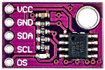
Capacitive Soil Sensor
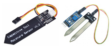
To measure soil moisture use an analog capacitive soil sensor. To improve the life of this sensor we will need to use one of the GPIO lines to power the sensor and another to read it. Not powering the sensor will help prevent corrosion of the probe.
Let's connect the sensor power to pin 9 and the analog input to pin 10.
First we will power the sensor by setting [g]pio pin [9] to an [o]utput of high [1].
Then set [g]pio pin [10] to an [a]nalog
input and read the voltages.
Finally we turn off the sensor by setting [g]pio pin [9] to an [o]utput of low [0].
>g9o1
ok

			>g10a
2.741
5.017
>g9o0
ok
>
The analog reading returned 2.741 volts when the sensor is dry. Now place the sensor in water and let's read it at 100% moisture.
>g10a
1.535
5.017
>
The analog reading returned 1.535 volts when the sensor is at 100% mositure. Using these two readings, you can use simple linear math to calculate the soil moisture percentage.
Moisture % = ((2.741 - input) / (2.741 - 1.535)) * 100
Note: Make sure you add a 250ms delay after you power the sensor on for it to initialize or you will read a zero voltage. If you send the commands on a single line add a delay by using the 'd' cmd.
>g9o1;d250;g10a;g9o0
ok
ok

			2.741
5.017
ok
>
Note: Pins 3,4 have a 2.2k pull up, and pins 6,8 have a 5.1k pull up already, so you can not use these pins for a soil moisture sensor, but you can power multiple soil moisture sensors from a single pin thus allowing you to connect more. Each GPIO pin can only current source 20mA, so the number you can power from a single pin will depend upon the current used by each soil moisture sensor.
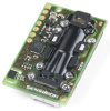
Ultrasonic HCSR04.
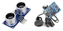
This is sensor type 6. There is a quick connect header at PL5 which is shared with pin 9 (Trigger) and 10 (Echo).
| subcmd | Function |
|---|---|
| r | Read |
| t6 | Type HCSR04 |
Lets [r]ead a HCSR04 [s]ensor on pin 10.
>s10t6;sr
HCSR04

			69.93978
>
The read returned the distance in cm.
ADC TEMT6000 Light.
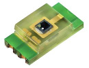
The TEMT6000 only recognizes visible light with wavelengths in the range of 390-700 nm (10 - 1000 lux). In addition to digital IO the IO Expander pins can also be used as analog inputs. This sensor is type 7.
Let's [r]ead a TEMT6000 light sensor on pin [16].
>s16t7;sr
TEMT6000

			104
>
The read returned the light in lux.
We can also read this sensor as an [a]nalog [G]PIO.
>g16a
0.517
4.946
>
The read returned the voltage read and the reference voltage. Using these values we can calculate the lux; (0.517 * 1000) / 4.946 = 104.5 lux. For accurate results it's important to use the voltage reference in your calculations, because it can change depending upon the sensor load.
Sensirion I2C HTU2x,SHT2x,SHT3x Temperature/Humidity.
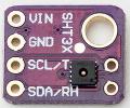
These Sensirion sensors all share a similar interface with some minor differences. These sensors also require an I2C bus. Directly the IO Expander does not support an I2C bus but with the 1-Wire® to I2C you can connect as many I2C devices as you like. I2C is a 3V3 bus that can only reach a couple of meters. To solve this cable length limitation the 1-Wire® to I2C has been implemented, so the bus is active only at the sensor end where it is deployed. Also dropping as many I2C buses off the 1-Wire® becomes very convenient resolving I2C address limitations.
HTU2x,SHT2x is sensor type 2.
| subcmd | Function |
|---|---|
| c[resolution] | Config[0-3] |
| d | Serial # |
| h[0,1] | Heater[0-On,1-Off] |
| o | Soft Reset SHT2x (New v1.15) |
| r | Read |
| t2 | Type HTU2x,SHT2x I2C=40 |
Using a Splitter we can connect to a 1-Wire® bus on pin [3], we need to first find and [s]elect the DS28E17 64-bit ID that we have our I2C sensor connected to.
>i3f
19765e03000000a2
>isa2

			19765e03000000a2
>
Now Lets [s]elect the [t]ype and [r]ead a SHT20 sensor.
>st2;sr
SHT2x

			40
26.6
45.81
>
The read returned the temperature in °C and humidity in %. The 40 after the sensor type is the default hexidecimal I2C address.
SHT3x is sensor type 3.
| subcmd | Function |
|---|---|
| d | Serial # (New v1.15) |
| h[0,1] | Heater[0-Off,1-On] |
| o | Soft Reset (New v1.15) |
| r | Read |
| t3 | Type SHT3x I2C=45 |
The SHT3x also allows an alternative I2C address of 45. Use the [s]ensor [t]ype command to specify the alternate address.
>st0345
SHT3x

			45
>
I2C Contol.
We can also communicate with the I2C device directly using the 'i' cmd.
| subcmd | Function | Mode |
|---|---|---|
| a[address] | Ascii Read[address] (New v1.15) | Hex |
| c[speed] | Config[0-100kHz,1-400kHz] | |
| f | Find only DS28E17 | |
| n | Scan Addresses | |
| o[n] | Speed[0-Standard,1-Overdrive] (New v1.15) | |
| r(address)[read[write]] | Read(address)[# bytes to read[write bytes]] | Hex |
| s | Select[64-bit ID] | Hex |
| w(address)(write) | Write(address)(write bytes) | Hex |
| ? | Device Revision |
Let's read the SHT20 using direct I2C commands at address 40. To read the temperature we send the command e3 and read 03 bytes. To read the humidity we send the command e5 and read 03 bytes.
>i3sa2;ir4003e3;ir4003e5

			19765e03000000a2
69ccac
6b5253
>
The first 2 bytes is the temperature reading of 0x69cc or 27084 and
0xac is the checksum.
So the temperature = -46.85 + 175.72 * (27084
/ 65536) = 25.7696 C
Atlas Scientific EZO™ Circuit Flow/Temperature/pH/ORP/Dissolved Oxygen/Conductivity (New v1.15).
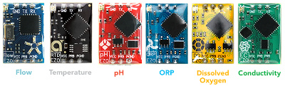
Using the EZO™ Circuits I2C data protocol, connect your Atlas Scientific lab/industrial sensor probe. Using the direct I2C commands interface easily to these circuits with writes and ascii reads.
Let's identify the pH circuit and then read the pH. After [w]riting the 'r'ead command [d]elay [900]ms before doing an [a]scii read.
>i4sc0;iw63"i";ia
198f1103000000c0
ok
?I,pH,2.11
>iw63"r";d900;ia

			ok
ok
01
5.744
>
The read returned the response code of 0x01 as well as the decimal pH reading.
Silicon Labs I2C Si7021 Temperature/Humidity.

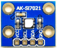
This sensor is also similar to the Sensirion SHT but with additional heater power control on the A20 or 2.0 firmware version.
Si7021 is sensor type 8.
| subcmd | Function |
|---|---|
| c[resolution] | Config[0-3] |
| d | ID |
| f | Firmware |
| h[0,1[power]] | Heater(0-Off,1-On)[0-f] |
| r | Read |
| t8 | Type Si7021 I2C=40 |
Let's [s]elect the 1-Wire® bus on pin [3] and then [s]elect the sensor [t]ype [8] and [r]ead a Si7021 sensor.
>i3sa2;st8;sr
19765e03000000a2

			Si702x
40
26.13
39.82
>
The read returned the temperature in °C and humidity in %.
Since the A20 or 2.0 firmware version has additional power control options, let's first check the [s]ensor [f]irmware and make sure we have 2.0. Then lets turn on the [h]eater and set the power to the maximum of 1111b or 0x0f.
>sf
2.0
>sh010f

			1
f
>
You can verify that the heater is on by the noticable temperature increase. Use the heater after a temperature/humidity reading if the humidity is high to ward off condensation from occuring and wait for the sensor temperature to normalize before reading it again. All humidity sensors exhibit some type of drift due to foreign or chemical contamination. To return or recondition the sensor, Silicon Labs recomends leaving the heater on for 24hrs.
Bosch I2C BMP180 Temperature/Pressure. (Depreciated v1.17)
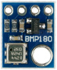
BMP180 is sensor type b.
| subcmd | Function |
|---|---|
| r | Read |
| tb | Type BMP180 I2C=77 |
Let's [s]elect the 1-Wire® bus on pin [3] and then [s]elect the sensor [t]ype [b] and [r]ead a BMP180 sensor.
>i3sa2;stb;sr
19765e03000000a2

			BMP180
77
26.5
99081
>
The read returned the temperature in °C and pressure in pa.
Bosch I2C BMP280 Temperature/Pressure. (New v1.17)

BMP280 is sensor type 18.
| subcmd | Function |
|---|---|
| r | Read |
| t18 | Type BMP280 I2C=76 |
Let's [s]elect the 1-Wire® bus on pin [3] and then [s]elect the sensor [t]ype [18] and [r]ead a BMP280 sensor.
>i3sa2;st18;sr
19765e03000000a2

			BMP280
76
28.58
99480
>
The read returned the temperature in °C and pressure in pa.
Bosch I2C BME280 Temperature/Humidity/Pressure. (New v1.17)

BME280 is sensor type 19.
| subcmd | Function |
|---|---|
| r | Read |
| t19 | Type BME280 I2C=76 |
Let's [s]elect the 1-Wire® bus on pin [3] and then [s]elect the sensor [t]ype [19] and [r]ead a BME280 sensor.
>i3sa2;st19;sr
19765e03000000a2

			BMP280
76
28.44
34.05
99534
>
The read returned the temperature in °C, humidity in %RH, and pressure in pa.
TAOS I2C TSL2561 Light. (Depreciated v1.17)
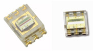
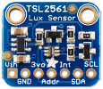
This light sensor combines a visible plus infrared into one. Able to detect light ranges from 0.1 Lux up to 40,000+ Lux!
This is sensor type 9 and the TSL2561CS is type a.
| subcmd | Function |
|---|---|
| c[Integration Time] | Config [0-13.7ms,1-101ms,2-402ms] |
| d | ID |
| p(0,1) | Power(0-Off,1-On) |
| r | Read |
| t9/ta[address] | Type TSL2561/TSL2561CS[29,39,49] I2C=39 |
Let's [s]elect the 1-Wire® bus on pin [3] and then [s]elect the sensor [t]ype [9] and [r]ead a TSL2561 light sensor.
>i3sa2;st9;sr
19765e03000000a2

			TSL2561
39
1087
>
The read returned the light in lux.
Note: When reading this sensor the gain control is automatic.
Ti I2C LM75 Temperature.
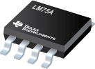
This is sensor type c.
| subcmd | Function |
|---|---|
| c[config,thyst,tos] | Config |
| r | Read |
| tc[address] | Type LM75[48-4f] I2C=48 |
Let's [s]elect the 1-Wire® bus on pin [3] and then [s]elect the sensor [t]ype [c] and [r]ead a LM75 temperature sensor.
>i3sa2;stc;sr
19765e03000000a2

			LM75
48
25
>
The read returned the temperature in °C.
What makes this sensor unique is the ability to control a GPIO (O.S.) at the sensor controlled by trip temperature data. This sensor behaves just like a thermostat. The output becomes active when the temperature exceeds tos and leaves the active state when the temperature drops below thyst. Use it to control a cooling fan.
Use the [c]onfig to set the config, thyst and tos registers.
Let's set the O.S. active low, thyst to 60.5 C, and tos to 75 C
>sc0,60.5,75
0

			60.5
75
>
Maxim I2C DS3132 RTC/Temperature.
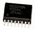
This is sensor type e.
| subcmd | Function |
|---|---|
| c[mm/dd/yy hh:mm:ss] | Config |
| r | Read |
| te | Type DS3231 I2C=68 |
Let's set the current date/time and read it back.
>i4s90;ste
199b590300000090

			DS3231
68
>sc8/8/21 21:43:00
8/8/21 21:43:00
>sr

			8/8/21 20:43:03

			28.25
>
The read returned the current date/time and the temperature in °C.
Atmel I2C AT24C32 32Kbps Serial EEPROM
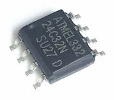
This is sensor type f.
| subcmd | Function | Hex |
|---|---|---|
| r(address)[bytes] | Read | |
| tf[address] | Type AT24C32[50-57] I2C=57 | |
| w(address)(n bytes) | Write(16-bit address)(n bytes) | Hex |
Let's set write and read to the serial EEPROM at address [0000]
>i4s90;stf
199b590300000090

			AT24C32
57
>sw0000"Hello"
ok
>sr00005
48656c6c6f
>
The read returned 'Hello' in hexadecimal.
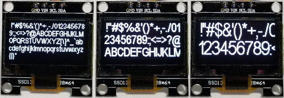
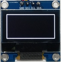
SSD1306 0.96", SSD1309 2.42" (New v1.14) I2C 128x64/128x32 Dot Matrix OLED/PLED Display
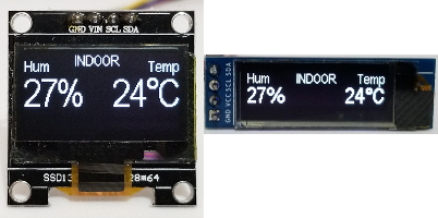
Note: To display this screen above please see putting it all together
This is sensor type 10.
| subcmd | Function | Mode |
|---|---|---|
| a(n) | Alignment(0-Left,1-Right,2-Center,3-Decimal) def=0 | |
| b(x,y,w,bitmap) | Bitmap (x,y,width,bitmap) | Dec |
| c[x,y,w,h] | Clear Screen [x,y,width,height] | Dec |
| d[x,y,string] | Display [x,y,string] | Dec |
| f[0-2] | Font Arial Narrow [0-10pt,1-16pt,2-24pt] def=2 | |
| h(x,y,length) | Horizontal Line (x,y,length) | Dec |
| i[w,h] | Initialize [width,height] def=128x64 | Dec |
| m(n) | Dim Screen (0-255) def=255 | Dec |
| n(0,1) | Invert (0-Black,1-White) | |
| o(0-2) | Color (0-Black,1-White,2-Inverse) def=1 | |
| p(0,1) | Power (0-Off,1-On) New v1.3 Beta | |
| t10[address] | Type SSD1306[3c-3d] I2C=3c | |
| v(x,y,length) | Vertical Line (x,y,length) | Dec |
| w(data) | Write (data) | Hex |
Note: x,y is zero based so if you are using a 128x64 display x is 0-127 and y is 0-63. The width and height are the actual size so on a 128x64 with is 1-128 and height is 1-64.
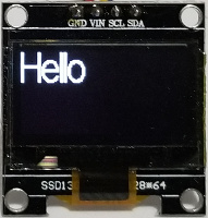
Before you can use the SSD1306 you must first [i]nitialize the display.
Let's first find all the 1-Wire® to I2C devices and then [s]elect, [t]ype, [i]nitialize, [c]lear the screen and [d]isplay "Hello".
>i4f

			199b590300000090
>is90;st10;si;sc;sd
SSD1306
3c
128

			64
ok
ok
>sd0,0,"Hello";sd
ok
ok
>
In order to update the display your last command should be a 'sd' or [s]ensor [d]isplay. All other drawing commands only updates a screen buffer in the IO Expander. There is only one screen buffer in the IO Expander so if you are handling multiple screens they need to be cleared and redrawn first before updating.
In the event that your display does not match the default COM pins configuration you can still change it manually using the [w]rite subcommand.
Let's change the COM pins configuration from a 128x64 to a 128x32 display.
>sw80da8022
>
The IO Expander supports the SSD1306 natively with full font support so that you don't have to waste your code space with font data tables. The non-proportional font supported is Arial Narrow 10pt, 16pt, and 24pt ascii characters space to '~' (decimal 32-126), and the degree symbol, decimal 248. The font heights are 13, 21, and 31 pixels high.
There are several ways to [a]lign the font string you need to display; left, right, center, and decimal. The alignment dictates the x,y location of the string. If you specify a right alignment then you need to specify the right most coordinates. If you exceed the display boundries the font will automatically be cropped.
To upload a bitmap to the SSD1306 use the 'b' subcommand specifing the starting location and width. The bitmap will byte wrap each line of binary data by the specified width.
Let's display a 30x30 bitmap of a sun, like the one shown below.
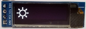
>is90;st10;si128,32;sc;sd
199b590300000090
SSD1306
3c
128

			32
ok
ok
>sb0,1,32,x00030000000300000003000000030000

			ok
>sb0,5,32,x0c0300c00e0001c007030380031fe300
ok
>sb0,9,32,x0078380000e01c0000c00c0001800600

			ok
>sb0,13,32,x0100020001000200fb00037cfb00037c
ok
>sb0,17,32,x01000200010002000180060000c00c00

			ok
>sb0,21,32,x00e01c0000703800031fe30007030380
ok
>sb0,25,32,x0e0001c00c0300c00003000000030000

			ok
>sb0,29,32,x0003000000030000
ok
>sd
ok
>
Or a far more efficient method to display a bitmap is sending the
bitmap data in String Mode.
Let's display the same sun bitmap using
String Mode on the Arduino.
					/* IO Expander

 *

 * Display Bitmap on a SSD1306 128x32

 *

 */


					#include "IOExpander.h"


					const
					unsigned
					char sun[]=
					{

  0x00,
					0x03, 0x00,
					0x00,
					0x00,
					0x03,
					0x00,
					0x00,
					0x00,
					0x03,
					0x00,
					0x00,
					0x00,
					0x03,
					0x00,
					0x00,

  0x0c,
					0x03, 0x00,
					0xc0,
					0x0e,
					0x00,
					0x01,
					0xc0,
					0x07,
					0x03,
					0x03,
					0x80,
					0x03,
					0x1f,
					0xe3,
					0x00,

  0x00,
					0x78, 0x38,
					0x00,
					0x00,
					0xe0,
					0x1c,
					0x00,
					0x00,
					0xc0,
					0x0c,
					0x00,
					0x01,
					0x80,
					0x06,
					0x00,

  0x01,
					0x00, 0x02,
					0x00,
					0x01,
					0x00,
					0x02,
					0x00,
					0xfb,
					0x00,
					0x03,
					0x7c,
					0xfb,
					0x00,
					0x03,
					0x7c,

  0x01,
					0x00, 0x02,
					0x00,
					0x01,
					0x00,
					0x02,
					0x00,
					0x01,
					0x80,
					0x06,
					0x00,
					0x00,
					0xc0,
					0x0c,
					0x00,

  0x00,
					0xe0, 0x1c,
					0x00,
					0x00,
					0x70,
					0x38,
					0x00,
					0x03,
					0x1f,
					0xe3,
					0x00,
					0x07,
					0x03,
					0x03,
					0x80,

  0x0e,
					0x00, 0x01,
					0xc0,
					0x0c,
					0x03,
					0x00,
					0xc0,
					0x00,
					0x03,
					0x00,
					0x00,
					0x00,
					0x03,
					0x00,
					0x00,

  0x00,
					0x03, 0x00,
					0x00,
					0x00,
					0x03,
					0x00,
					0x00

					};


					void setup()

					{

  Serial.begin(115200);


  SerialCmdDone("i4s90;st10;si128,32;sc;sd");

  SerialDisplayBitmap(0,0,30,30,sun);

  SerialCmdDone("sd");

					}


					void loop()

					{

					}
Or on the Raspberry Pi in Python.
#!/usr/bin/env python

import ioexpander


ioexpander.ser.flushInput()


sun = b'\x00\x03\x00\x00\x00\x03\x00\x00\x00\x03\x00\x00\x00\x03\x00\x00' \

      b'\x0c\x03\x00\xc0\x0e\x00\x01\xc0\x07\x03\x03\x80\x03\x1f\xe3\x00' \

      b'\x00\x78\x38\x00\x00\xe0\x1c\x00\x00\xc0\x0c\x00\x01\x80\x06\x00' \

      b'\x01\x00\x02\x00\x01\x00\x02\x00\xfb\x00\x03\x7c\xfb\x00\x03\x7c' \

      b'\x01\x00\x02\x00\x01\x00\x02\x00\x01\x80\x06\x00\x00\xc0\x0c\x00' \

      b'\x00\xe0\x1c\x00\x00\x70\x38\x00\x03\x1f\xe3\x00\x07\x03\x03\x80' \

      b'\x0e\x00\x01\xc0\x0c\x03\x00\xc0\x00\x03\x00\x00\x00\x03\x00\x00' \

      b'\x00\x03\x00\x00\x00\x03\x00\x00'


ioexpander.SerialCmdDone(b'i4s4a;st13;si;sc;sd')

ioexpander.SerialDisplayBitmap(0,0,30,30,sun)

ioexpander.SerialCmdDone(b'sd')
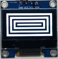
Use the c[o]lor with the [c]lear subcommand to create quick border effects.
>i4s90;st10;si;sc;sd

			199b590300000090
SSD1306
3c
128
64
ok
ok
>so0;sc;so1;sc5,5,118,54;so0;sc10,10,108,44;so1;sc15,15,98,34

			0
ok
1
ok
0
ok
1
ok
>so0;sc20,20,88,24;so1;sc25,25,78,14;so0;sc30,30,68,4;sd

			0
ok
1
ok
0
ok
ok
>
For quick flashing effects use the i[n]vert subcommand.
>sn1;d100;sn0;d100;sn1;d100;sn0;d100;sn1;d100;sn0

			ok
ok
ok
ok
ok
ok
ok
ok
ok
ok
ok
>
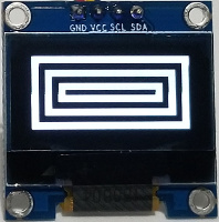
Use the [h]orizontal and [v]ertical line draw subcommands to draw a single pixel border frame.
>i4s90;st10;si;sc;sd

			199b590300000090
SSD1306
3c
128
64
ok
ok
>sh0,0,128;sh0,63,128;sv0,0,64;sv127,0,64;sd

			ok
ok
ok
ok
ok
>
You can add as many screens as you want on the 1-Wire® bus using the 1-Wire® to I2C with the same I2C address or via different address on the I2C bus. Using the 1-Wire® bus you can easily install them much farther apart than any I2C bus would support.
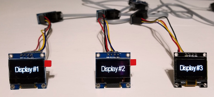
Let's put all the commands together and display the humidity and temperature on the OLED display as shown at the start of this sensor.
>i4s90;st10;si;sc;sd

			199b590300000090
SSD1306
3c
128
64
ok
ok
>sf0;sa2;sd64,0,"INDOOR";sa0;sd0,5,"Hum";sa1;sd127,5,"Temp"

			0
2
ok
0
ok
1
ok
>sf2;sa0;sd0,20,"27%";sa1;sd127,20,"24",248,"C";sd

			2
0
ok
1
ok
ok
>
Microchip I2C MCP9600,MCP6901 Thermocouple Temperature

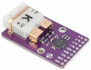
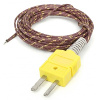
This Thermocouple temperature sensor allows you to read type K, J, T, N, S, E, B and R.
This is sensor type 11.
| subcmd | Function | Mode |
|---|---|---|
| a(n)[,config,hysteresis,limit] | Alert(1-4)[,config,hysteresis 0-255°C,limit] | Dec |
| c[type,filter,device] | Config [Type 0-7:KJTNSEBR,Filter Coefficients 0-7,Device Configuration] | Hex |
| d | ID/Revision | |
| r | Read | |
| t11[address] | Type MCP9600[60-67] I2C=67 | |
| w | Raw ADC |
Let's select this [s]ensor and [r]ead it. The default sensor type is K.
>i4s90;st11;sr
199b590300000090

			MCP9600
67
28.1875
18.875
0.3645
4f
>
The read returned the hot junction temperature of 28.1875°C, cold junction temperature of 18.875°C, ADC measurement of 0.3645mV and status register bits.
You can also control the four individaully controlled temperature alert limits with hysteresis, set to detect a rising or falling temperature of either the hot or cold junction. The corresponding alert limit outputs can also be enabled for temperature status indicators.
Let's set the temperature alert limit 1 to compare the hot junction temperature of 15.25°C, with a hysteresis of 2°C.
>sr
19.4375
18.8125

			0.0209
4f
>sa1,0,2,15.25
0
2
15.25
1
>
The read returned the settings for temperature alert 1. The last value of 1 is the alert status where TH>TALERT1
Support for
Firmware Revison 13 (New v1.13)
Microchip finally
fixed the clock stretching issue at 100kHz. When the MCP9600 is selected
it will automatically detect the revision and if the firmware >=
13 it will no longer repeat the sequential read until the second byte
is different. Basically much faster reads.
HX711 Load Cell Weight (New v1.13)
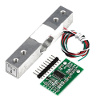
This Load Cell Amplifier sensor allows you to easily measure weight by reading the difference in voltage caused by the resistance change of the load cell.
This is sensor type 12.
| subcmd | Function | Mode |
|---|---|---|
| g[gain] | Gain [32,64,128 def=128] | Dec |
| p(0/1) | Power (0-Off,1-On) | |
| r[times,tare,scale] | Read [#Times Average,Tare/Offset,Scale/Divisor] | Dec |
| t12 | Type HX711 |
To accurately read a weight we first have to figure out the tare or offset and then using a known weight calculate the scale.
Let's first select this [s]ensor and [r]ead it 20 times with nothing on the scale.
>s6t12
HX711
>sr20

			82064
>
The read returned the current average ADC value which is our tare or offset value. If when adding weight decreases the read value then you have reversed the A or B -/+ wires.
tare = 82064
Then place a known weight (44g) on the scale and read it again 20 times.
>sr20
87832
>
Using these two readings we can now calculate the scale;
scale = (87832-82064)/44 = 131.09
Now using the tare and scale we can now accurately read any other weight. Let's read another known weight (84g) to verify our values.
>sr20,82064,131.09

			83.95
>
Note: You can do repeated reads without having to enter the tare and scale again or to reset the values just reselect the sensor type.
Debug: If you are constantly reading -/+8388608 the ADC is fully saturated. Check your wiring. Powered, read the excitation voltage across E -/+, it should read slightly less than the input voltage. With the power removed measure the resistance A or B -/+ wires you should read about 1k.
SH1106 1.3" I2C 128x64 Dot Matrix OLED/PLED Display (New v1.13)
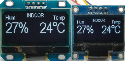
The image above is the 1.3" SH1106 OLED display on the left, compared to the 0.96" SSD1306 OLED display on the right. The commands are the same as the SSD1306 OLED Display with the same resolution of 128x64 except larger.
This is sensor type 13.
| subcmd | Function | Mode |
|---|---|---|
| a(n) | Alignment(0-Left,1-Right,2-Center,3-Decimal) def=0 | |
| b(x,y,w,bitmap) | Bitmap (x,y,width,bitmap) | Dec |
| c[x,y,w,h] | Clear Screen [x,y,width,height] | Dec |
| d[x,y,string] | Display [x,y,string] | Dec |
| f[0-2] | Font Arial Narrow [0-10pt,1-16pt,2-24pt] def=2 | |
| h(x,y,length) | Horizontal Line (x,y,length) | Dec |
| i[w,h] | Initialize [width,height] def=128x64 | Dec |
| m(n) | Dim Screen (0-255) def=255 | Dec |
| n(0,1) | Invert (0-Black,1-White) | |
| o(0-2) | Color (0-Black,1-White,2-Inverse) def=1 | |
| p(0,1) | Power (0-Off,1-On) | |
| t13[address] | Type SH1106[3c-3d] I2C=3c | |
| v(x,y,length) | Vertical Line (x,y,length) | Dec |
| w(data) | Write (data) | Hex |
TAOS I2C TSL2591 Light (New v1.14)
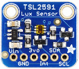
This light sensor combines a visible plus infrared into one. Able to detect light ranges from 188 uLux up to 88,000 Lux with a 600,000,000:1 dynamic range!
This is sensor type 14.
| subcmd | Function |
|---|---|
| c[Integration Time] | Config [0-100ms,1-200ms,2-300ms,3-400ms,4-500ms,5-600ms] |
| d | ID |
| p(0,1) | Power(0-Off,1-On) |
| r | Read |
| t14[address] | Type TSL2591[29] I2C=29 |
Let's [s]elect the 1-Wire® bus on pin [4] and then [s]elect the sensor [t]ype [14] and [r]ead a TSL2591 light sensor.
>i4s4a;st14;sr
19ce5d030000004a

			TSL2591
29
23.27
>
The read returned the light in lux.
Note: When reading this sensor the gain control is automatic.
TAOS I2C TCS34725 RGB Light (New v1.14)
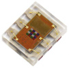
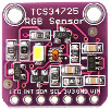
This light sensor provides a digital return of red, green, and blue (RGB) with an IR blocking filter. This highly sensitive sensor has a 3,800,000:1 dynamic range.
This is sensor type 15.
| subcmd | Function |
|---|---|
| c[Integration Time] | Config [0-614.4ms-ff-2.4ms] |
| d | ID |
| p(0,1,2,3,4) | Power(0-Off,1-On AIEN=0,2-On AIEN=1,3-On AIEN=x,4-On AIEN=x,AEN=0) |
| r | Read |
| t15[address] | Type TCS34725[29] I2C=29 |
If using an LED with the TCS34725 use AIEN to control it. To turn off the LED jumper LED and INT, and use the 'p2' subcmd.
Let's [s]elect the 1-Wire® bus on pin [4] and then select the [s]ensor [t]ype [15] and then [s]ensor [r]ead a TCS34725 light sensor.
>i4s4a;st15
19ce5d030000004a

			TCS34725
29
>sr
17205
21171
19789
56089
192

			1
>
The read returned the raw red, green, blue and clear light sensed with the ATIME and gain (x1, x4, x16, x60) control for the reading. Use these values to calculate the color temperature and lux.
Note: When reading this sensor the integration time and gain control are automatic starting from the configured integration time down.
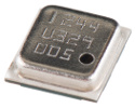
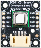
Sensirion I2C SCD30 CO2 Temperature/Humidity (New v1.14)
Low Power NDIR CO2 sensor (0 - 40,000 ppm) with integrated temperature and humidity sensor. Dual-channel detection for superior accuracy and stability.
This is sensor type 16.
| subcmd | Function | Mode |
|---|---|---|
| c(Option)[,Parameter] | Config Options: 1-Continuous Measurement[,Pressure Compensation (700-1200) in mBar. 0-No Pressure] 2-Stop Continuous Measurement 3-Measurement Interval[,Interval (2-1800) in seconds] 4-Data Ready 5-Automatic Self Calibration[,0-Deactivate 1-Activate] 6-Force Recalibration Factor[,FRC (400-2000) in ppm] 7-Temperature Offset[,Ticks (0.01-25) in °C] 8-Altitude Compensation[,Height Over Sea Level in m] 9-Firmware Version 10-Soft Reset |
Dec |
| f | Firmware Version | |
| i | Initialize (Continuous Measurement With a 2 Second Interval) | |
| r | Read | |
| t16[address] | Type SCD30[61] I2C=61 |
Let's [s]elect the 1-Wire® bus on pin [4] and then select the [s]ensor [t]ype [16], [s]ensor [i]nitialize and then [s]ensor [r]ead the SCD30 CO2 sensor.
>i4s4a;st16;si
19ce5d030000004a

			SCD30
61
ok
>sr
404.4158
24.1508
44.6334
>
The read returned the CO2 in ppm, temperature in °C and humidity in %.
Note: It is recommended to use this sensor with a median filter to inprove reading consistency.
Sensirion I2C SCD40,SCD41 CO2 Temperature/Humidity (New v1.17)
Low Power Photoacoustic CO2 sensor (0 - 40,000 ppm) with integrated temperature and humidity sensor. High accuracy and smallest form factor.
This is sensor type 1c.
| subcmd | Function | Mode |
|---|---|---|
| c(Option)[,Parameter] | Config Options: 1-Start Periodic Measurement 2-Stop Periodic Measurement 3-Temperature Offset[,Temperature Offset in °C] 4-Sensor Altitude[,Pressure in m] 5-Ambient Pressure,Pa in mBar/100 6-Forced Recalibration, Target Concentration ppm CO2 7-Automatic Self Calibration[,0-Deactivate 1-Activate] 8-Start Low Power Periodic Measurement 9-Data Ready Status 10-Persist Settings 11-Serial Number 12-Self Test 13-Factory Reset 14-Reinit 15-Single Shot (SCD41) 16-Single Shot RHT Only (SCD41) |
Dec |
| i | Initialize (Start Periodic Measurement) | |
| r | Read | |
| t1c[address] | Type SCD40[62] I2C=62 |
Let's [s]elect the 1-Wire® bus on pin [4] and then select the [s]ensor [t]ype [1c], [s]ensor [i]nitialize and then [s]ensor [r]ead the SCD40 CO2 sensor.
>i4s4a;st1c;si
19ce5d030000004a

			SCD40
62
ok
>sr
1248
24.06
51.39
>
The read returned the CO2 in ppm, temperature in °C and humidity in %.
Note: When issuing a config subcmd the SCD40 is put into idle mode except for Data Ready Status; i.e. Stop Periodic Measurement. To Start Periodic Measurements again issue the config 1 or 7 option.
433MHz RF Transmitter (New v1.16)
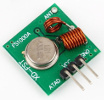
Use a 433MHz RF transmitter to control wireless power sockets.
This is sensor type 17.
| subcmd | Function | Mode |
|---|---|---|
| c[times,bits,delay,zerohigh,zerolow,onehigh,onelow] | times-# of Transmissions bits-# of Bits (0-32) delay-us Delay Between Transmissions zerohigh-us Zero High zerolow-us Zero Low onehigh-us One High onelow-us One Low |
Dec |
| w(data) | Write (data) | Hex |
Refer to our Hacking a 433MHz RF Power Socket for additional information.
PCF8574/PCF8574A 8-bit I2C Expander (New v1.17)
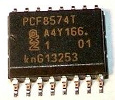
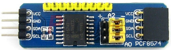
PCF8574 is sensor type 1a.
| subcmd | Function | Mode |
|---|---|---|
| r[bit] | Read [bit 0-7] | |
| w(byte) | Write (byte) | Hex |
| t1a[address] | Type PCF8574[20-27] I2C=20 Type PCF8574A[38-3F] |
Hex |
Let's [s]elect the 1-Wire® bus on pin [3] and then [s]elect the sensor [t]ype [1a] and [r]ead a PCF8574 sensor.
>i3sa2;st1a;sr
19765e03000000a2

			PCF8574
20
7f
>
The read returned the 8-bit input with bit 7 forced low.
Now let's set bit 2 as an output low, but to keep bit 7 as an input make sure you set it high.
>swfd
ok
>
To verify our input and output let's read the inputs again.
>sr
7d
>
The read returned bit 7 as an input forced low, and bit 2 as an output forced low.
ADS1015 12-bit 4-Channel ADC I2C Expander (New v1.17)
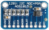
ADS1015 is sensor type 1b.
| subcmd | Function | Mode |
|---|---|---|
| c[fsr,r1,r2] | Config [fsr-(0-6.144V,1-4.096V,2-2.048V,3-1.024V),r1-Resistor 1 Divider,r2-Resistor 2 Divider] | Dec |
| r(channel) | Read (Channel 0-3) | |
| t1b[address] | Type ADS1015[48-4B] I2C=48 | Hex |
Let's [s]elect the 1-Wire® bus on pin [3] and then [s]elect the sensor [t]ype [1b] and [c]onfig an ADS1015 sensor.
>i3sa2;st1b;sc
19765e03000000a2

			ADS1015
48
1
0
0
>
The read returned the FSR (full-scale range) of 1 (4.096V), and R1 and R1 are both zero as no voltage divider.
Since the ADS1015 is powered by 3.3V we need an FSR of more than 3.3V to read the full range. Let's connect the 3.3V into AIN0 and [r]ead AIN[0] of the sensor.
>sr0
3.304
>
If you have a voltage divider connected to the ADC input you can use R1 and R2 in the configuration to do the voltage calculations for you.
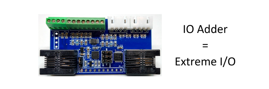
The IO Adder uses a voltage divider on all the ADS1015 inputs to measure up to 12V. To configure the sensor set the following configuration values.
>sc2,1200,220
2
1200
220
>
The read returned the FSR of 2 (2.048V), R1=1.2K, and R2=220 ohms. With these values the maximum input voltage would be:
12V * (220 / (1200 + 220) = 1.859V.
Analog Keypad (New v2.1 Plus)
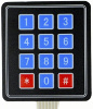

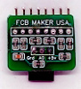
Use an FCB Maker to convert 7 or 8 digital pins to 1 analog pin. Then connect a 3x4 or 4x4 digital keypad.
KEYPAD is sensor type 1d.
| subcmd | Function | Mode |
|---|---|---|
| c[threshold,key] | Config [threshold,key] | Dec |
| d[time] | Debounce(time in ms) | Dec |
| r | Read | |
| w | Raw |
To first use the keypad it must be configured. To do this we will assign the analog levels to each key.
Let's [c]onfigure a 3x4 Keypad on pin [2].
>i2s1d
KEYPAD
>sc18,"1",329,"2",598,"3",1000,"4",1183,"5",1346,"6",1603,"7",1723,"8",1833,"9",2009,"*",2093,"0",2172,"#"

			18,1

			329,2

			598,3

			1000,4

			1183,5

			1346,6

			1603,7

			1723,8

			1833,9

			2009,*

			2093,0

			2172,#

			>sd100
ok
>
Also don't forget to add a debounce of 100ms. At this time you can only specify one keypad configuration for all keypads connections to the IO Expander. To clear the configuration use a threshold=0 and key=0; i.e. >sc0,0
Once configured you can now press the keys on the keypad and just read back the keys. Let's enter '1278' on the Keypad and do a [r]ead.
>sr
1278
>
Note: The IO Expander will only retain the last 8 keys pressed until read. The user will have to combine the reads to process the final input. If no key is pressed, nothing will be returned.
We can remove the debounce by specifying a detect time of zero.
>g2d0
ok
>
To figure out the analog level for each key on your keypad use the raw subcmd. Let's depress and hold the '1' key while we read the ra[w] analog value.
>sw
18
>
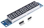
TM1637 6 Digit LED Display (New v2.1 Plus)
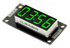
This sensor requires the use of two pins. Select D1 as your DIO pin and the IO Expander will automatically select D2 as your CLK pin. You can also connect this sensor to the Z-Wire GPIO bit streaming on pins P0,P1.
TM1637 is sensor type 1e.
| subcmd | Function | Mode |
|---|---|---|
| b[brightness] | Brightness [0-7] | Dec |
| d | Display String | String |
| o | Order[0,1,2,3,4,5] | Dec |
To use a 4 digit display just select the [s]ensor [t]ype, and [d]isplay.
>s10t1e
TM1637
>sd"12:30"
ok
>
Note: To display the decimal place just insert it at the location needed. Some clock displays do not have the decimal places wired."
To display on a 6 digit display you may need to first [o]rder the segments, then display the digits.
>s10t1e;so2,1,0,5,4,3
TM1637
2
1
0
5
4
3
>sd"  98.6F"
ok
>
Note: The ordering is global for all displays connected.
ZGPIO 3-Channel ADC/IO (New v2.1 Plus Z-Wire)
Please see our Z-Wire I2C/IO product
ZGPIO is sensor type 1f.
HT16K33 16*8 LED Controller Driver (New v2.1 Plus Z-Wire)


This sensor requires the use of the Z-Wire to I2C/IO module to support the required 5V I2C levels.
HT16K33 is sensor type 20.
| subcmd | Function | Mode |
|---|---|---|
| b[brightness][,blinkrate] | Brightness [0-7], Blinkrate [0-3] | Dec |
| c | Clear | |
| d | Display Font String (14 Segment) | String |
| i | Initialize | |
| s | Display Seven Segment String | String |
| w | Write Raw 16-bit | Hex |
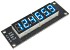
MAX7219 8-Digit LED Display Driver (New v2.2 Plus Z-Wire v1.3)
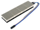
This sensor requires the use of the Z-Wire to ZGPIO bit streaming on pins P0,P1,P2.
MAX7219 is sensor type 21.
| subcmd | Function | Mode |
|---|---|---|
| b[brightness] | Brightness [0-15] | Dec |
| c | Clear | |
| d | Display Dot Matrix String | String |
| i[n[,sl,md,mt]] | Initialize[number(1-16)[,scanlimit(0-7),marquee delay(ms),matrix translation(0-7)]] 8x8 Matrix Translation Table (def=5). 0 - None 1 - Reverse Column 2 - Reverse Row 3 - Reverse Row & Column 4 - Switch Row and Column 5 - Switch Reverse Row and Column 6 - Switch Row and Reverse Column 7 - Switch Reverse Row and Reverse Column |
Dec |
| m | Marquee Dot Matrix String | String |
| o | Order[0,1,2,3,4,5,6,7] | Dec |
| s | Display Seven Segment String | String |
Note: Please be aware of counterfeit MAX7219 chips.
- Require decoupling capacitors to help stability.
- Consume a lot more current resulting in voltage drops.
- Only able to cascade a few chips.
- Require inline resistors to minimize ringing.
- Require separate power rails.
INA260 Ti I2C Precision Digital Current and Power Monitor (New v2.4)
INA260 is sensor type 22.
| subcmd | Function | Mode |
|---|---|---|
| a[type,limit,enable] | Alert type 0 - None 1 - Conversion Ready 2 - Power Over-Limit 3 - Bus Voltage Under-Voltage 4 - Bus Voltage Over-Voltage 5 - Under Current Limit 6 - Over Current Limit limit Power 419430 mW Bus Voltage +-40958.75 mV Current +-40958.75 mA enable(bit) 0 - Latch 1 - Polarity |
Dec |
| c[avg,vbct,shct,mode[,rst]] | Configuration avg - Averaging Mode 0 - 1 1 - 4 2 - 16 3 - 64 4 - 128 5 - 256 6 - 512 7 - 1024 vbct - Bus Voltage Conversion Time 0 - 140 us 1 - 204 us 2 - 332 us 3 - 588 us 4 - 1.1 ms 5 - 2.116 ms 6 - 4.156 ms 7 - 8.244 ms shct - Shunt Current Conversion Time 0 - 140 us 1 - 204 us 2 - 332 us 3 - 588 us 4 - 1.1 ms 5 - 2.116 ms 6 - 4.156 ms 7 - 8.244 ms mode - Operating Mode 0 - Power-Down (or Shutdown) 1 - Shunt Current, Triggered 2 - Bus Voltage, Triggered 3 - Shunt Current and Bus Voltage, Triggered 4 - Power-Down (or Shutdown) 5 - Shunt Current, Continuous 6 - Bus Voltage, Continuous 7 - Shunt Current and Bus Voltage, Continuous rst - 1 to Reset |
Dec |
| f | Firmware | Hex |
| r | Read Current(mA), Voltage(mV), Power(mW) |
Let's [s]elect the Z-Wire bus on pin [4] and then [s]elect the sensor [t]ype [22] and [r]ead an INA260 sensor.
>z4s67;st22;sr
64825d67

			INA260
40
58.75
11975
700
>
The read returned the current used by the IO Expander, Z-Wire to I2C, and the IAN260 of 58.75 mA, Voltage of 11975 mV (12V), and Power of 700 mW.
System Commands.
System sub-commands are prefixed with the # cmd character.
| subcmd | Function | Mode |
|---|---|---|
| b[address] | Board Address[0-255] | Dec |
| e[0,1] | Echo[0-Off,1-On] | |
| f | Firmware Version | |
| l(pins) | Loopback(bits 19-0) (Depreciated v1.17) | Hex |
| r | Reset | |
| s | Serial # | |
| t | Onboard Temperature | |
| v | Voltage |
Let's read the onboard [t]emperature and [v]oltage.
>#t;#v
30.75

				4.946
>
The read returned the onboard temperature in °C, and voltage.
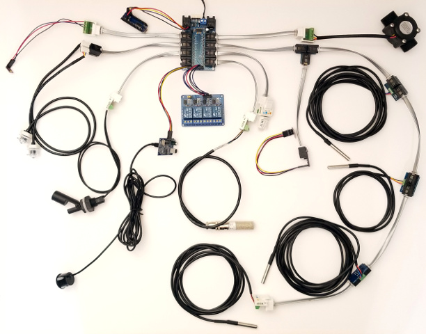
Connect All the Sensors
Now let's connect all the sensors that we just covered onto one IO Expander and there's still plenty of room to connect more! Pins 1,5,11, and 15 were not even used, and you can continue adding as many 1-Wire® sensors as needed. Not enough room no problem, connect multiple IO Expanders together for virtually unlimited IO expansion!
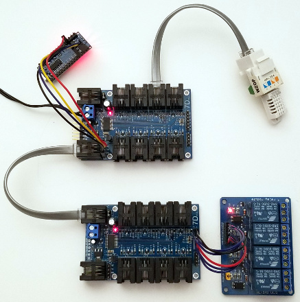
Connect Multiple IO Expanders Together
The IO Expander has a very unique and powerful feature. Not only does it support 8-bit data but it also supports multi-drop 9-bit data. With 9-bit data, each IO Expander is assigned a unique board address (1-255). Connecting up to 255 IO Expanders together truly makes this system expandable! If the IO Expanders need to be connected with a long wire it's recommended to use the IO Extender which will truly extend your system.
Every time a command is sent it must be prefixed with the board address with the 9th bit set. This is an address byte. If your MCU does not support 9-bit you can still use 8-bit by sending an address byte using the mark and space parity as the 9th bit.
So let's switch to 9-bit addressess by using the system command '#', and assigning a [b]oard address.
>#b1
1
>
The return is the assigned board #. This board number is stored in non-volatile storage so you only have to set it one time and it will always remember it, even if the board is powered down or disconnected.
When a IO Expander is first powered it is in 8-bit mode. In order to switch it to 9-bit mode you will have to send it a zero byte. This zero byte is the same if it is in 8-bit or 9-bit data mode, so sending it multiple times has no effect if you are already in 9-bit data mode. If you assign the wrong board address connect it stand alone and power it up in 8-bit data mode, then change the board address to the correct one.
Let's connect two IO Expander boards together. The first board with a DHT22 temperature/humidity sensor, and the second with a x4 relay board. We will control relay 1 on board two like a thermostat to turn a fan on at 26°C using the temperature read from board one.
Arduino 9-bit
The Atmega328P supports 9-bit, but the Arduino HardwareSerial library does not. Use the HardwareSerial9Bit library that has some minor modification to the Arduino HardwareSerial library so that you can control multiple IO Expander boards. This library supports 8-bit data with 9-bit addressing only. To simplify development to multiple boards use the accompanying IOExpander9Bit library.
Download
HardwareSerial9Bit.zip v1.0 library.
Download
IOExpander9Bit.zip v1.4 library.
/* IO Expander sketch optimized

 *

 * Read a DHT22 Humidity/Temperature Sensor on Board 1, Pin 6 and

 * Switch relay 1 on/off on Board 2 like a thermostat.

 *

 */


#include <HardwareSerial9Bit.h>

#include <SoftwareSerial.h>

#include "IOExpander9Bit.h"


SoftwareSerial swSerial(8,7);


char relay = 0;

char cmd[128];


void setup() {

  Serial9Bit.begin(115200, SERIAL_9N1);

  swSerial.begin(115200);

  swSerialEcho = &swSerial;

  Serial9Bit.write(0);                          // Set IO Expanders to 9-bit

  if (!SerialCmdDone(2, "rsf"))                 // [s]et all [r]elays off. Make sure expander boards set to zero (>eb0).

    swSerial.println("IO Expander 2 not found");

}


void loop() {

  float temp, humidity;


  if (SerialDebugControl(cmd, sizeof(cmd))) return;


  if (SerialCmdDone(1, "s6t5")) {              // cmd [s]ensor on pin [6], [t]ype [5]

    SerialCmd(1, "sr");                        // cmd [s]ensor [r]ead

    if (SerialReadFloat(&temp) &&              // read temperature

        SerialReadFloat(&humidity)) {          // read humidity

      SerialReadUntilDone();                   // wait for cmd done

      if (temp >= 26) {

        if (!relay) {

          if (SerialCmdDone(2, "r1o")) {       // [r]elay [1] [o]n

            swSerial.println("Relay On");

            relay = 1;

          }

        }

      }

      else if (temp <= 25) {

        if (relay) {

          if (SerialCmdDone(2, "r1f")) {       // [r]elay [1] of[f]

            swSerial.println("Relay Off");

            relay = 0;

          }

        }

      }

      swSerial.println(temp, 1);

      swSerial.println(humidity, 1);

    }

  }

  else swSerial.println("IO Expander 1 not found");

}
To disable 9-bit just set your board # back to zero.
Raspberry Pi 9-bit
The Raspberry Pi does not support 9-bit, so we will have to use 8-bit mark and space parity. Only problem is that the Raspbian OS does not support mark and space parity either, so for the Pi4 that uses the BCM2711 we will have to use some undocumented code and use what is called stick parity that is selected by bit 7 (SPS) in the LCRH register.
By default the primary serial port on the header pins 14 and 15 uses UART1 (MiniUART/ttyS0) which does not support any parity bits. We will have to switch the pins to use a different UART0 (ttyAMA0) as the primary serial port instead.
To do this add the following lines to your /boot/config.txt file.
				enable_uart=1

				dtoverlay=disable-bt
Run the following command on your console as well, to disconnect the bluetooth from UART0.
pi@raspberrypi:~ $ sudo systemctl disable hciuart
Using the ioexpander9bit.py Python module you can now perform multi-drop 9-bit addressing on the Raspberry Pi and connect multiple IO Expanders together.
Download ioexpander9bit.py v1.1 Python Module.
#!/usr/bin/env python

import ioexpander9bit


ioexpander9bit.ser.flushInput()


# set IO Expander to 9-bit

ioexpander9bit.ser.write(b'\0')

# switch to simulated 9-bit mode using SPACE and MARK parity

ioexpander9bit.SerialSPACEParity()


relay = False


if ioexpander9bit.SerialCmdDone(2, b'rsf') is None:

    print("IO Expander 2 not found")


while 1:

    if ioexpander9bit.TelnetControl(b''):

        continue


    if ioexpander9bit.SerialCmdDone(1, b's6t5') is not None:

        ioexpander9bit.SerialCmd(1, b'sr')

        temp = ioexpander9bit.SerialReadFloat()

        humidity = ioexpander9bit.SerialReadFloat()

        ioexpander9bit.SerialReadUntilDone()


        if temp > 26 and not relay:

            if ioexpander9bit.SerialCmdDone(2, b'r1o') is not None:

                print("Relay On")

                relay = True

        else:

            if temp <= 25 and relay:

                if ioexpander9bit.SerialCmdDone(2, b'r1f') is not None:

                    print("Relay Off")

                    relay = False


        print(temp, ",", humidity)

    else:

        print("IO Expander 1 not found")
Downloadable Firmware
Keep up to date with the latest firmware by connecting your IO Expander to either PL6, IN, or OUT to an available USB to Serial TTL port on your PC and update it with the Windows Application over the internet. Newer versions of firmware will include bug fixes and support for additional sensors. This application will search all your available COM ports for an IO Expander and automatically update it. Never connect it to a DB9 serial port on your PC as this may damage the IO Expander. Use the recommended FTDI TTL-232R-5V USB to Serial TTL cable for programming your IO Expander.
Or use your Arduino as a USB to serial cable! Since you are shorting Reset to GND, no programming required!
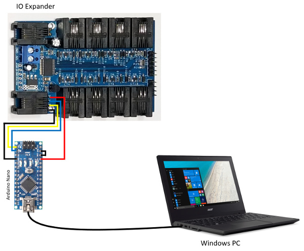
Note: Please make sure your echo is enabled so that the firmware updater software can find your IO Expander.
>#e1
1
>
Firmware Downloader v2.3 Windows Update Program. Now with built in Terminal support!
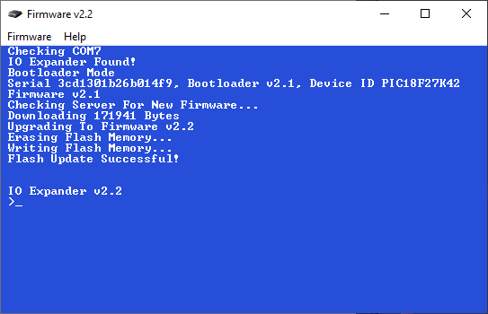
Version History of Firmware v2.4
1-Wire is a registered trademark of Maxim Integrated Products, Inc.