Zeven Development
 This is an image title
 This is an image title
 This is an image title
 This is an image title
 This is an image title
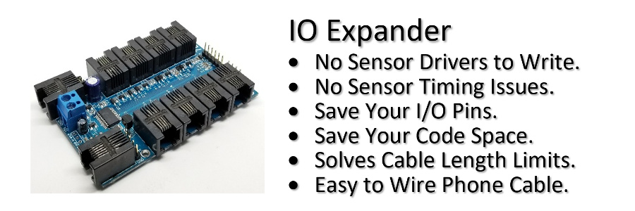
9-Bit Multidrop Communications
Connect multiple IO Expanders together using a 9-bit multidrop communications.
RS232 is typically used as a point to point (P2P) communications network. To amplify the signal to go long distances, transceivers (7-12V) were used, which constrained the communications to P2P. With the removal of the transceivers for a cheaper RS232 using CMOS transistor-transistor logic (TTL) levels (3.3-5V), it now became possible to implement point to multipoint (P2MP).
A P2MP network can be created by using a Master to multiple Slaves with 9-bit data where the 9th bit is used to indicate an address byte. Every Slave has a unique board address. The Master in our case will be an Arduino, and the Slaves our IO Expanders. All the slaves are listening for an address byte, and if it matches with the board address, then the following data bytes are accepted. All the other Slaves will ignore the data because it is not addressed to them.
You can connect a single transmit line (Tx) to multiple receive lines (Rx), but you cannot connect multiple Tx lines to a single Rx line; you will have contention. To solve this problem, in 9-bit mode all the Slaves Tx lines are disabled (open-collector) until the Slave is addressed. After the response is sent to the Master the Tx line is disabled again thus allowing another Slave to be addressed. Essentially all the Slaves take their turn to transmit to the Master one at a time.
Let's look at a logic analyzer capture/decode of the 9-bit communications.
The first byte transmitted from the Arduino is 0x101. The 9th bit is set so the following 8-bits or byte is the board number of 0x01. After reading the address byte, board #1 will now turn on it's transmitter, echo the command, send the response, and finally disable the transmitter.
The capture shows that the [e]xpander relay [1] was turned [o]n.
>e1o
ok
>
IO Expander Setup for 9-bit Mode
Let's setup two IO Expanders in 9-bit mode, each connected to a x16 relay board.
First connect board #1 to your computer using a terminal application send the following command:
>#b1;eb1
1
1
>
Then connect board #2 to your computer and send the following command:
>#b2;eb1
2
1
>
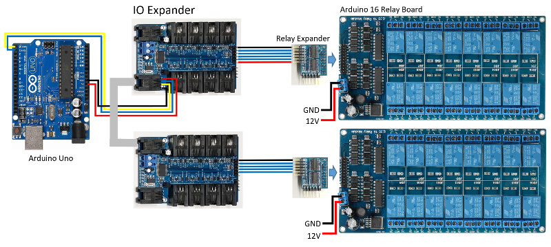
Wire up the Arduino and IO Expanders as shown in the following diagram. The phone wire connecting the IO Expanders together is 6P6C straight through.
9-bit Wiring Diagram
9-bit in Action
The Atmega328P supports 9-bit, but the Arduino HardwareSerial library does not. Use the HardwareSerial9Bit library that has some minor modification to the Arduino HardwareSerial library so that you can control multiple IO Expander boards. This library supports 8-bit data with 9-bit addressing only. To simplify development to multiple boards use the accompanying IOExpander9Bit library.
Download
HardwareSerial9Bit.zip v1.0 library.
Download
IOExpander9Bit.zip v1.4 library.
9-bit Arduino Code
/* IO Expander sketch optimized

 *

 * Relay 9-bit with IO Expanders!

 *

 */


#include <HardwareSerial9Bit.h>

#include "IOExpander9Bit.h"

#include <avr/wdt.h>


#define MAX_BOARDS    2


char cmd[10];


void setup()

{

  Serial9Bit.begin(115200, SERIAL_9N1);


  delay(100);                               // Wait 100 ms for IO Expander Title

  while (Serial9Bit.available()) Serial9Bit.read(); // Flush RX buffer


  Serial9Bit.write(0);                      // Set IO Expanders to 9-bit by sending zero

  delay(1);


  wdt_enable(WDTO_8S);


  // Turn off all the relays on all the boards

  for (int board = 1; board <= MAX_BOARDS; board++) {

    SerialCmdDone(board, "esffff");         // Clear all the relays

  }

}


void loop()

{

  static int board = 1;

  static int relay = 1;


  if (board <= MAX_BOARDS) {

    sprintf(cmd, "e%do", relay);            // Turn on the relay

    SerialCmdDone(board, cmd);


    delay(200);                             // Delay, must be less than 8 sec or add a loop.


    sprintf(cmd, "e%df", relay);            // Turn off the relay

    SerialCmdDone(board, cmd);


    if (++relay > 16) {                     // Select the next relay

      relay = 1;

      if (++board > MAX_BOARDS)             // Select the next board

        board = 1;

    }

  }

  wdt_reset();

}
Note: Do not use the USB port on the Arduino Uno since it is shared with the Tx,Rx lines. Instead use the ICSP port for programming.