Zeven Development
 This is an image title
 This is an image title
 This is an image title
 This is an image title
 This is an image title

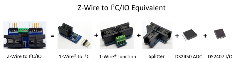
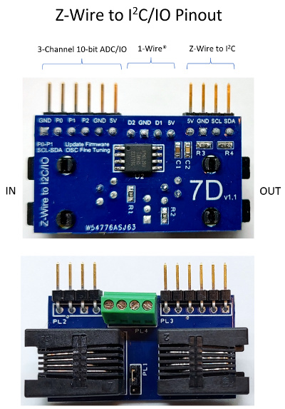
Z-Wire to I2C/IO (New 2023!)
Connect I2C/IO sensors to the Z-Wire to I2C/IO adapter.
Z-Wire or Zeven Wire is a new one wire bus protocol that can coexist on a Maxim's 1-Wire® bus but is not compatible. Z-Wire replaces the short comings of the expensive and hard to get DS28E17 1-Wire® to I2C, DS28E18 1-Wire® to I2C/SPI, and the now obsolete DS2407 Dual Addressable Switch and DS2450 Quad A/D Converter equivalent. The purpose of this product is to consolidate, and have only one sensor junction at each location.
It uses it's own protocol and will only work with an IO Expander Plus v2.1.
This new device allows you to connect any I2C sensor, 1-Wire® DS18B20 temperature sensor, TM1637 LED display, and Soil Moisture ADC capacitive sensor all at the same time on a single data wire.
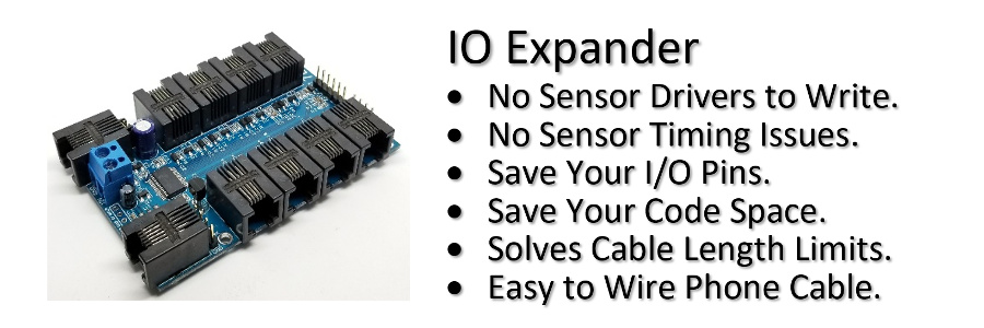
Feature List
- Z-Wire bus can coexist on the same 1-Wire® bus.
- Connect multiple I2C buses to your Z-Wire bus on the IO Expander.
- I2C bus only at the end so it solves the limited cable length of I2C.
- Use multiple Z-Wire to I2C/IO adapters to connect multiple I2C sensors with the same I2C address.
- I2C bus is 5V instead of the DS28E17/DS28E18 3V3.
- 4.7kΩ I2C bus pull-ups on R3 and R4.
- PL1 jumper to select D1 or D2.
- Software selectable I2C bus speeds of 100kHz or 400kHz.
- Z-Wire Low or High(default) speed.
- Full Send and Receive CRC checking. DS28E17 does not support read I2C data CRC checking
- Compliant I2C Clock Stretching. DS28E18 does not support the industry standard I2C Clock Stretching at all.
- 32-bit programmable addresses instead of Maxim 1-Wire® devices using fixed 64-bit ROM addresses. Results in faster searching and device selection.
- 3 Digital IO/10-bit ADC pins.
- 20mA current sourcing on P0 and P1. 2mA only on P3.
- Z-Wire requires 3-wires to work; 5V, GND, and a single bidirectional data pin. Parasitic control is not supported.
- Advanced brownout detection. Fixes DS28E17 lockup issues that required additional reset pin control.
- Hardware watchdog monitoring for maximum reliability.
- Downloadable firmware. Keep up to date with the latest updates.
- Low standby power 5mA typical with P0-P2 as inputs and low speed; 18mA with P0-P2 as outputs or high speed.
- 39.4mm x 22.2mm.
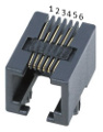
| Pin | Function |
|---|---|
| 1 | NC |
| 2 | 5V |
| 3 | D1 |
| 4 | Gnd |
| 5 | D2 |
| 6 | NC |
The following I2C sensors are supported by the IO Expander.
| # | Sensor Type |
|---|---|
| 2 | HTU2x,SHT2x Temperature/Humidity |
| 3 | SHT3x Temperature/Humidity |
| 8 | Si702x Temperature/Humidity |
| 9 | TSL2561 Light |
| a | TL2561CS Light |
| b | BMP180 Temperature/Pressure |
| c | LM75 Temperature |
| e | DS3231 RTC/Temperature |
| f | AT24C32 Serial EEPROM |
| 10 | SSD1306/SSD1309 OLED Display |
| 11 | MCP9600 Thermocouple Temperature |
| 12 | HX711 Load Cell Weight |
| 13 | SH1106 OLED Display |
| 14 | TSL2591 Light |
| 15 | TCS34725 RGB Light |
| 16 | SCD30 CO2 Temperature/Humidity |
| 18 | BMP280 Temperature/Pressure |
| 19 | BME280 Temperature/Humidity/Pressure |
| 1a | PCF8574 8-bit Expander |
| 1b | ADS1015 12-bit 4-Channel ADC Expander |
| 1c | SCD40,SCD41 CO2 Temperature/Humidity |
| 20 | HT16K33 16*8 LED Controller Driver |
| 21 | MAX7219 8-Digit LED Display Driver (New Z-Wire v1.3) |
| 22 | INA260 Ti Precision Digital Current and Power Monitor. (New v2.4) |
Using the IO Expander you can communicate with the I2C device directly using the 'z' cmd or connect many of the supported I2C sensors using the 's' cmd.
| subcmd | Function | Mode |
|---|---|---|
| a[address] | Ascii Read[address] | Hex |
| c[speed] | Config[0-100kHz,1-400kHz] | |
| f | Find only Z-Wire | |
| l[count] | Oscillator Calibration | Dec |
| n | Scan Addresses | |
| o[n] | Speed[0-Low,1-High] | |
| r(address)[read[write]] | Read(address)[# bytes to read[write bytes]] | Hex |
| s | Select[32-bit ID] | Hex |
| w(address)(write) | Write(address)(write bytes) | Hex |
| ? | Device Revision | |
| # | 32-bit Address | Hex |
For this tutorial we have connected x4 Z-Wire to I2C/IO, x2 1-Wire® to I2C, and x4 DS18B20 1-Wire® Temperature Sensors all connected on pin 4.
Find all the Devices
First let's [f]ind all the [Z]-Wire devices on pin [4].
>z4f
6446bb89
6446bb5d
6446bb33
6446bbaf
>
Next let's [f]ind all the 1-Wire® to [i]2c devices on pin [4].
>i4f
19ce5d030000004a
19c1350500000048
>
Finally let's [f]ind all the DS18B20 1-Wire® [T]emperature Sensors on pin [4].
>t4f
28dadd16a8013c9c
28f18216a8013c28
283534e50800006e
28cf8216a8013cd6
>
As you can see the Z-Wire functionality is similar to the 1-Wire® devices except it only has a 32-bit address.
Z-Wire I2C SHT3x Temperature/Humidity Sensor
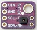
Connect an SHT3x temperature/humidity sensor to the I2C connector PL2 of the Z-Wire device 6446bbaf and read it.
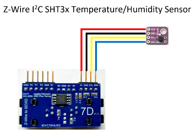
[S]elect the [Z]-Wire device 6446bb[af] on pin [4]; select the [s]ensor [t]ype [3]; finally do a [s]ensor [r]ead.
>z4saf;st3;sr
6446bbaf
SHT3x
44
25.01
53.73
>
1-Wire® DS18B20 Temperature Sensors
You can connect two 1-Wire® DS18B20 Temperature Sensors to PL4
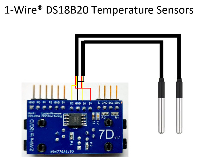
If one of the temperature sensors is on pin 4 (D1) then the other will be pin 3 (D2).
[T]emperature sensor on pin [4], [s]elect DS18B20 28dadd16a8013c[9c]; perform a [t]emperature measurmen[t]; finally do a
[t]emperature [r]ead.
>t4s9c;tt;tr
28dadd16a8013c9c
ok
27.5625
>
The functionality of PL4 is identical to the 1-Wire® Junction product.
Z-Wire ZGPIO Sensor
The Z-Wire Digital/ADC pins P0-P2 are accessed by selecting the ZGPIO sensor which is type 1f.
| subcmd | Function | Mode |
|---|---|---|
| a[channel,count] | Analog Read[channel 0-2,1-255 Count Average] | Dec |
| b(data) | Bit Stream Byte 0:Pins(1-3),1-2:Delay in us,3-n:Alternating Pin Byte Data | Hex |
| p(data) | SPI Bit Stream Byte 0:Packet Size(1-20),1-n:Data (New v1.3) | Hex |
| r[pin] | Read[Pin] | |
| w(dir,output) | Write(Direction Bits P2-P0:(0-Input,1-Output),Output Bits P2-P0:(0-Low,1-High)) | Dec |
Connect 5V on P0 of the Z-Wire device 6446bbaf and read it.
[S]elect the [Z]-Wire device 6446bb[af] on pin [4]; select the [s]ensor [t]ype [1f]; [s]ensor [w]rite [0,0] for P2-P0 as an inputs; finally do a [s]ensor [r]ead of P[0].
>z4saf;st1f;sw0,0;sr0
6446bbaf
ZGPIO
1
>
This returns a 1 or high on P0. If you don't specify a pin number and just do an 'sr' it will return P2-P0 with P0 being bit 0.
We can also do an analog read on P0 by doing a [s]ensor [a]nalog
read of P[0].
>sa0
4.862
4.882
>
The first reading is the voltage on P0, and the second reading is the reference voltage of the IO Expander.
Let's specify P0 as an output and drive it high.
[S]elect the [Z]-Wire device 6446bb[af] on pin [4]; select the [s]ensor [t]ype [1f]; [s]ensor [w]rite [1,1] for P0 as an output, and P2-P1 as inputs with P0 being high.
>z4saf;st1f;sw1,1
6446bbaf
ZGPIO
ok
>
Note: If you specify a high output on an input pin it will act as a weak pull up.
Z-Wire Soil Moisture Sensor
Connect a soil moisture sensor to GND,P0(VCC),and P1(AOUT) of PL3.
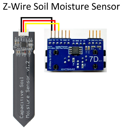
To improve the life of this sensor we will need to use P0 to power the sensor and P1 to read it. Not powering the sensor will help prevent corrosion of the probe.
First power the sensor by setting P0 as an output and high, then read [s]ensor [a]nalog on P[1]. Finally turn off the sensor by setting P0 low.
>z4saf;st1f;sw1,1
6446bbaf
ZGPIO
ok

			>sa1
2.816
4.922
>sw1,0
ok
>
The analog reading returned 2.816 volts when the sensor is dry. Now place the sensor in water and let's read it at 100% moisture.
>sa1
1.35
4.922
>
The analog reading returned 1.35 volts when the sensor is at 100% mositure. Using these two readings, you can use simple linear math to calculate the soil moisture percentage.
Moisture % = ((2.816 - input) / (2.816 - 1.35)) * 100
Note: Make sure you add a 250ms delay after you power the sensor on for it to initialize or you will read a zero voltage. If you send the commands on a single line add a delay by using the 'd' cmd.
>z4saf;st1f;sw1,1;d250;sa1;sw1,0
6446bbaf
ZGPIO
ok
ok

			2.816
4.922
ok
>
You can connect another soil moisture sensor to GND,P0(VCC),and P2(AOUT), then [s]ensor read [a]nalog on P[2].
Z-Wire TM1637 6-Digit LED Display
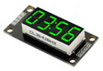
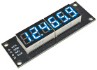
Using the Z-Wire Bit Streaming feature you can also use P0 and P1 to output to a TM1637 LED Display.
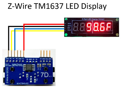
[S]elect the [Z]-Wire device 6446bb[af] on pin [4]; select the [s]ensor [t]ype [1e]; [s]ensor [o]rder [2,1,0,5,4,3]; [s]ensor [d]isplay [" 98.6F"]. By first selecting the Z-Wire device the IO Expander will automatically select pin P0 and P1 to bit stream the CLK and DIO output.
>z4saf;st1e;so2,1,0,5,4,3;sd"  98.6F"
6446bbaf
TM1637
2
1
0
5
4
3
ok
>
You can also perform your own Bit Stream on the Z-Wire ZGPIO sensor to perform the same output.
>z4saf;st1f
6446bbaf
ZGPIO

			>sb020500eac0aa01ac80f560550056f1aafeaa78d50055005a00aa00ab0055c055fc6a19aaffad8355ff55fc9e0daae6aa06cf07
ok
>
Bit Stream example as:
| Byte | Description |
|---|---|
| 02 | 2 Pins P0 and P1 |
| 0500 | 5us Delay Between Bits |
| ea | CLK Bits [0:7] |
| c0 | DIO Bits [0:7] |
| aa | CLK Bits [8:15] |
| 01 | DIO Bits [8:15] |
| ... |
Note: For longer bit streams use ascii mode to compact your hex data.
Z-Wire MAX7219 8-Digit LED Display Driver (New v1.3)
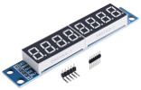
Using the Z-Wire SPI Bit Streaming feature you can also use P0,P1 and P2 to output to a MAX7219 LED Display.
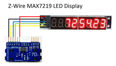
[S]elect the [Z]-Wire device 6446bb[af] on pin [4]; select the [s]ensor [t]ype [21]; [s]ensor [i]nitialize [1]; [s]ensor [o]rder [7,6,5,4,3,2,1,0]; [s]ensor [s]even segment display [" 7254.23"]. By first selecting the Z-Wire device the IO Expander will automatically select pin P0,P1 and P2 to bit stream the CLK, DIN and CS output.
>z4saf;st21;si1;so7,6,5,4,3,2,1,0;ss"  7254.23"
6446bbaf
MAX7219

			1
7
0
5
7
6
5
4
3
2
1
0
ok
>
You can also connect to a MAX7219 8x8 LED Matrix. This is a x4 MAX7219 cascaded together.
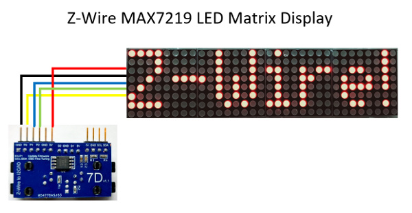
>z4saf;st21;si4;sd"Z-Wire!"
6446bbaf
MAX7219
4
7
0

			5
ok
>
Note: If you are using a differently wired 8x8 LED matrix and it does not translate correctly, try a different Matrix Translation
si4,7,0,x where x can be 0-7.
You can also perform your own SPI Bit Stream (CLK is automatic, and CS is between each Packet, you only need to specify the Data!) on the Z-Wire ZGPIO sensor to perform the same output.
>z4saf;st1f
6446bbaf
ZGPIO

			>sp080100010001000100024c02170228020f0302031203540301045e04120454040205520532055505e4064c06d3064406080740070007440708084008020844080f
ok
>
SPI Bit Stream example as:
| Byte | Description |
|---|---|
| 08 | 8 Byte Packets |
| 01 | Digit 0 Bits [15:7] 4th MAX2719 |
| 00 | DP A B C D E F G Bits [7:0] |
| 01 | Digit 0 Bits [15:7] 3rd MAX2719 |
| 00 | DP A B C D E F G Bits [7:0] |
| ... |
With the SPI Bit Stream you can set any LED you want in the 8x8 LED Matrix. Since you directly handling the SPI Bit Stream, you will also have to take care of the 8x8 Matrix Translation.
Note: For longer bit streams use ascii mode to compact your hex data.
Marquee in action using x12 MAX7219 cascaded!
>z4saf;st21;si12;sm"The quick brown fox jumped over the lazy dog"
6446bbaf
MAX7219
12
7
0

			5
ok
>
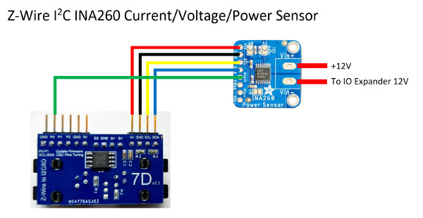
INA260 I2C Precision Digital Current and Power Monitor (New v2.4)
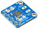
Connect an INA260 Precision Digital Current and Power Monitor sensor to the I2C connector PL2 of the Z-Wire device 6446bbaf and read it.
[S]elect the [Z]-Wire device 6446bb[af] on pin [4]; select the [s]ensor [t]ype [22]; finally do a [s]ensor [r]ead.
>z4saf;st22;sr
6446bbaf
INA260
40
58.75
11975
700
>
Z-Wire Alert Power Monitoring with the INA260
To use the Alert feature of the INA260 connect the Alert pin to the Z-Wire board, P0 of PL2. This allows us to only have to check the P0 pin instead of reading the INA260 continuously for a condition.
Let's first setup the Alert on the INA260 for an Under-Voltage condition type [3], of [11000]mV (11V), with latching enabled. Latching allows for the Alert pin to be enabled if it occurs, until you clear it.
>z4saf;st22
6446bbaf
INA260
40
>sa3,11000,1
3
11000
1
>
Now let's check the P0 pin. The Adafruit INA260 does not come with an external pullup on the Alert pin so we will have to use the weak internal pullup on the Z-Wire board.
>st1f;sw0,1;sr0
ZGPIO
ok
1
>
The state is high which is correct. Now using a bench supply drop the voltage to the IO Expander to 10V. Let's take another look at the pin.
>sr0
0
>
The Alert pin went active low because the voltage dropped below the Alert limit of 11V. To reset the Alert just read the Alert
>st22;sa
INA260
40
3
11000
1
>
Note: For the latched Alert to be properly cleared, the Alert condition must no longer be true.
Z-Wire Low Standby Power
To place the Z-Wire board into the lowest standby power mode, make sure P0-P2 are inputs and you are in low speed mode.
[S]elect the [Z]-Wire device 6446bb[af] on pin [4]; select the [s]ensor [t]ype [1f]; [s]ensor [w]rite [0,0] where P0-P2 are inputs; [Z]-Wire m[o]de is low [0] speed.
>z4saf;st1f;sw0,0;zo0
6446bbaf
ZGPIO
ok
0
>
To return back to high speed send the 'zo1' command. This single command will change all Z-Wire devices on the same wire.
Z-Wire Maximum Wire Length
The Z-Wire board has been designed/tested to work reliably up to 50ft using a 2.2K pullup. To achieve greater wire lengths up to 100ft or more, replace the pullup resistor with a 1.1K.
Z-Wire Oscillator Calibration
The internal oscillator has already been fine tuned at production/testing to meet the required 1 us timing requirements, but in the event of an unforseen field failure you can fine tune the internal oscillator yourself. Using the IO Expander v2.1 with the following wiring and jumper on SCL-SDA, perform your own Oscillator Calibration.
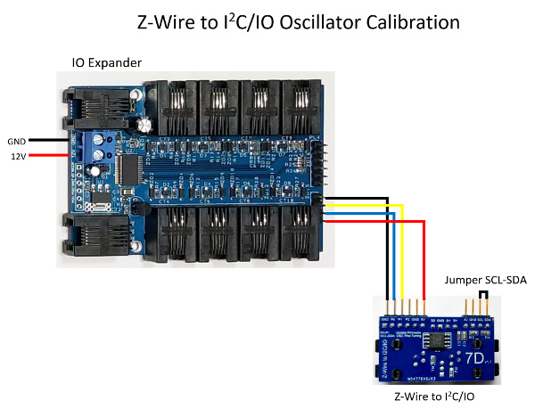
Note: The jumper SCL-SDA must be installed before you power up the Z-Wire board.
Perform a [Z]-Wire ca[l]ibration
>zl
0.1880

			-0.4672
-0.1472
>
The returned values are the percentage variances to the desired frequency. If you require a more accurate measurement please specify a calibration count.
Z-Wire Downloadable Firmware
Keep up to date with the latest firmware by connecting your Z-Wire to I2C/IO as shown in the following wiring to an available USB to Serial TTL port on your PC and update it with the Windows Firmware Downloader application over the internet. Newer version of the firmware will include bug fixes and new features. Use the recommended FTDI TTL-232R-5V USB to Serial TTL cable for programming your Z-Wire to I2C/IO, or use your Arduino as a USB to serial cable! Since you are shorting Reset to GND, no programming required!
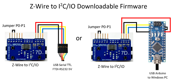
Note: The jumper P0-P1 must be installed before you power up the Z-Wire board.
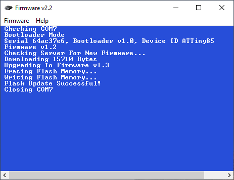
Firmware Downloader v2.2 Windows Update Program
Version History of Firmware v1.3
1-Wire is a registered trademark of Maxim Integrated Products, Inc.